
Working method of combined type industrial dust remover enabling air outlet to perform reverse dust blowing

A technology for industrial dust collectors and working methods, applied in chemical instruments and methods, combined devices, separation methods, etc., can solve the problems of weak dust adsorption effect of filter bags, high dust removal efficiency, poor dust removal effect, etc. Processing time, the effect of enhancing the dust removal effect

Inactive Publication Date: 2017-12-19
太仓市除尘设备厂
View PDF5 Cites 9 Cited by
  • Summary
  • Abstract
  • Description
  • Claims
  • Application Information

AI Technical Summary

Problems solved by technology

At present, electrostatic precipitators and bag dust collectors are widely used. If they are used alone, the effect of dust removal and purification is not ideal.
The electrostatic precipitator has the advantages of simple structure, convenient operation and maintenance, etc., but its biggest disadvantage is that the dust collection efficiency is not very high; the bag type dust collector has high dust removal efficiency, and the dust removal process is mainly completed by the filter bag. When using an external filter type dust collector, The dust-laden air flow flows from the outside of the filter bag to the inside, and the dust is captured and deposited on the outer surface of the filter bag. However, as the dust increases on the outer surface of the filter bag, the effect of the filter bag on absorbing dust becomes weaker. The time in the dust collector is short, the dust is difficult to be completely absorbed, the dust removal effect is not good, and the air is easy to take the dust out at the air outlet

Method used


Image

  • Working method of combined type industrial dust remover enabling air outlet to perform reverse dust blowing
  • Working method of combined type industrial dust remover enabling air outlet to perform reverse dust blowing

Examples


Embodiment

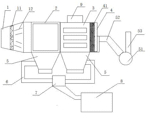
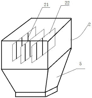
[0019] Such as figure 1 Shown is a working method of a combined industrial dust collector with reverse dust blowing at the air outlet. The combined industrial dust collector includes a dust air inlet 1, an electrostatic precipitator 2, a bag filter 3, a purified air outlet 4 and a blowback device 5. The dust air inlet 1 is set on the left side of the electrostatic precipitator 2, the bag filter 3 is set on the right side of the electrostatic precipitator to communicate with it, the purified air outlet is set on the right side of the bag filter 3, and the blowback device 5 is set on the purification 4 air outlets. Both the electrostatic precipitator 2 and the bottom of the bag filter 3 are provided with a dust collection tank 5, and the side of the dust collection tank 5 is also provided with a spray water pipe 6, and the other end of the spray water pipe 6 is connected to the water outlet of the water pump 7, and the water pump 7 The water inlet is connected with water storag...


PUM


Abstract

The invention relates to a working method of a combined type industrial dust remover enabling an air outlet to perform reverse dust blowing. The combined type industrial dust remover comprises a dust air inlet, an electrostatic dust remover, a cloth bag dust remover, a purified air outlet and reverse blowing devices, wherein the dust air inlet is formed in the left side of the electrostatic dust remover; the cloth bag dust remover is arranged on the right side of the electrostatic dust remover, and is communicated with the electrostatic dust remover; the purified air outlet is formed in the right side of the cloth bag dust remover; and the reverse blowing devices are arranged at the purified air outlets. According to the combined type industrial dust remover disclosed by the invention, reverse blowing fans of the reverse blowing devices are used for blowing wind from the purified air outlet to the cloth bag dust remover, so that the processing time of dusty gas in the cloth bag dust remover is prolonged, the dust removing effect is strengthened, and the situation that dusts are taken out from the air outlet can also be avoided.

Description

technical field [0001] The invention relates to the technical field of dust removal, in particular to a working method of an industrial dust collector with reverse blowing dust at an air outlet. Background technique [0002] In order to protect the environment, industrial waste gas needs to be dedusted and purified. At present, electrostatic precipitators and bag filter are widely used. If they are used alone, the effect of dust removal and purification is not ideal. The electrostatic precipitator has the advantages of simple structure, convenient operation and maintenance, etc., but its biggest disadvantage is that the dust collection efficiency is not very high; the bag type dust collector has high dust removal efficiency, and the dust removal process is mainly completed by the filter bag. When using an external filter type dust collector, The dust-laden air flow flows from the outside of the filter bag to the inside, and the dust is captured and deposited on the outer su...

Claims


Application Information

Patent Timeline
IPC IPC(8): B01D50/00B01D46/04B01D46/42
CPCB01D46/04B01D46/4236B01D50/00Y02A50/2351
Inventor 陆维光
Owner 太仓市除尘设备厂
Features
  • Generate Ideas
  • Intellectual Property
  • Life Sciences
  • Materials
  • Tech Scout
  • Unparalleled Data Quality
  • Higher Quality Content
  • 60% Fewer Hallucinations
Learn More