Stirring device with stirring plate

A technology of stirring device and stirring plate, which is used in mixers with rotating stirring devices, accessories of mixers, transportation and packaging, etc., can solve the problems of material blockage and non-flowing, uneven mixing of materials, etc., to ensure transportability and reduce noise pollution. , Improve the effect of human control safety performance

Inactive Publication Date: 2017-12-19
兰溪市酉泽饲料技术服务有限公司
View PDF4 Cites 1 Cited by
  • Summary
  • Abstract
  • Description
  • Claims
  • Application Information

AI Technical Summary

Problems solved by technology

However, in practical applications, the stirring shaft of the device has a blind area, which may cause uneven mixing of materials, and may cause some materials to block and not flow, so the stirring effect needs to be improved.

Method used


Image

  • Stirring device with stirring plate
  • Stirring device with stirring plate
  • Stirring device with stirring plate

Examples


Embodiment 1

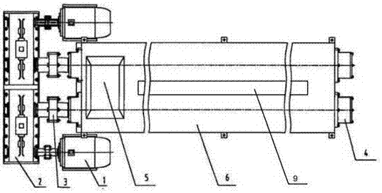
[0023] Such as Figure 1~6 As shown, a stirring device with a stirring plate includes a motor 1 and a stirring box 6, the output shaft of the motor 1 is connected to a reduction box 2, the output shaft of the reduction box 2 is connected to a coupling 3, and the coupling 3 is connected to a stirring shaft 4. The stirring shaft 4 is arranged in the stirring box 6, and the motor 1, the reduction box 2, the shaft coupling 3 and the stirring shaft 4 are arranged symmetrically around the center line of the stirring box 6 respectively. The structure connection of the device of the present invention is simple, easy to operate and stable Realize mixing without blind zone, good mixing and diversion effect, long service life, suitable for popularization and use.

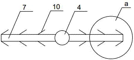
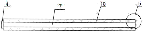
[0024] The surface of the stirring shaft 4 is obliquely connected with a stirring plate 7, the angle β between the stirring plate 7 and the stirring shaft 4 is 75°, the stirring shaft 4 is obliquely connected to the surface of...

Embodiment 2

[0032] Such as Figure 1~6 As shown, a stirring device with a stirring plate, in actual work, the motor 1 is turned on, and the material is continuously poured into the stirring box 6 through the feed port 5, and the motor 1 drives the coupling 3 to rotate through the reduction box 2, The coupling 3 drives the stirring shaft 4 to rotate, and the two motors 1 turn in the opposite direction and have the same speed, so that the stirring shaft 4 also rotates in the opposite direction but at the same speed, thereby driving the stirring plate 7 on the stirring shaft 4 to roll in the opposite direction. Stir the material in the opposite direction, and give the material a forward force while stirring, so that the material is pushed to the discharge port while being stirred. During the stirring process, the stirring situation inside the mixing box 6 can be observed in real time through the observation window 9 , place the collection device at the discharge port, the uniformly stirred m...


PUM


Abstract

The invention provides a stirring device with a stirring plate. The stirring device includes a motor and a stirring box, the output shaft of the motor is connected with a reduction gearbox, the output shafts of the reduction gearbox are connected with shaft couplings, the shaft couplings are connected with stirring shafts, the stirring shafts are arranged in the stirring box, and the motor, the reduction gearbox, the shaft couplings and the stirring shafts are respectively symmetrically arranged around the center line of the stirring box. The device has the advantages of simple structure connection, convenience operation, realization of increase of the material overturning range by using the stirring plate, improvement of the stirring quality, good anticorrosion property in the stirring shafts and the stirring plate, good stirring diversion effect, long service life, and suitableness for promoted use.

Description

technical field [0001] The invention relates to a stirring device, in particular to a stirring device with a stirring plate. Background technique [0002] The mixing device is a dosing box in the water treatment project, which is mainly used for stirring, dissolving and storing various chemicals, and then dosing the liquid medicine to each dosing point through a metering pump or a water injector. The shape of the dosing box is divided into square and round, and the material is polyethylene (PE). It is formed at one time by rotational molding technology, and the installation position of the metering pump and the mixer is preset on the upper part. [0003] Prior art such as Chinese Invention Patent Authorization Announcement Document, the authorized announcement number is CN 101342766 B, which discloses a continuous powerful mixer, including symmetrically arranged double motors and double reducers, which are respectively connected with the double reducers for operation. Two a...

Claims


Application Information

Patent Timeline
Patent Type & Authority Applications(China)
IPC IPC(8): B01F7/04B01F15/00C09D161/14C09D5/10C09D7/12
CPCC09D161/14C09D5/10C08K13/02C08K2003/2241C08K3/34B01F27/0531B01F27/191B01F27/701B01F35/31
Inventor 孙琦
Owner 兰溪市酉泽饲料技术服务有限公司
Why Eureka
Try Eureka