Horizontal heater structure with high heat utilization rate

A utilization rate and heater technology, which is applied to heat exchanger shells, lighting and heating equipment, heat exchange equipment, etc., can solve the problems of high steam temperature requirements, waste of resources, low heat exchange efficiency, etc., to meet the requirements of reasonable utilization, Increase the heat exchange time and increase the effect of the conveying process

Inactive Publication Date: 2017-12-19
ANHUI CHUNHUI INSTR CABLE GROUP
View PDF8 Cites 9 Cited by
  • Summary
  • Abstract
  • Description
  • Claims
  • Application Information

AI Technical Summary

Problems solved by technology

[0002] In the existing mother liquid heater structure, the tank body is mostly placed vertically, and its inlet and outlet ports are mostly set at both ends, that is, the mother liquid only has one-way heat exchange from the feed port through the heat transfer pipe to the discharge port. In the process, the heat transfer pipe is in contact with the steam at the end of the time, the heat transfer efficiency is low, and at the same time, it has high requirements for the temperature of the steam, and it cannot achieve the rational utilization of the steam, resulting in a waste of resources. In order to solve this problem, the existing technology The use of baffles set at misplaced intervals in the tank body, although the heat exchange efficiency has been increased to a certain extent, the steam heat energy still cannot be used reasonably, and it does not conform to my country's energy-saving and emission-reduction policies.

Method used


Image

  • Horizontal heater structure with high heat utilization rate
  • Horizontal heater structure with high heat utilization rate

Examples


Embodiment Construction

[0014] See attached picture.

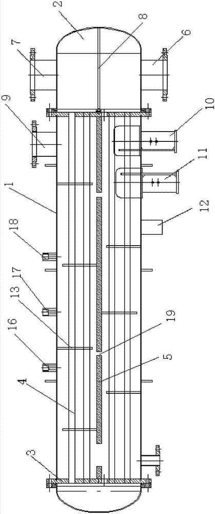
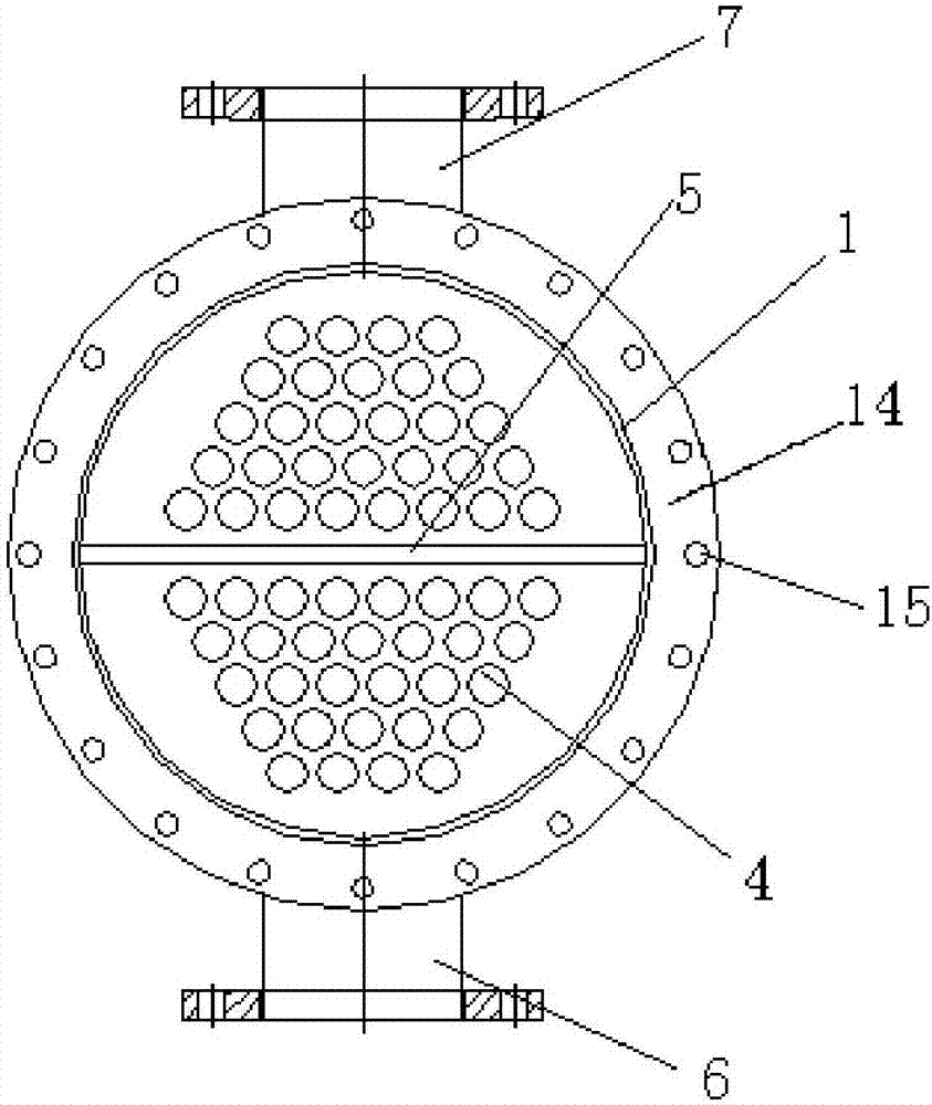
[0015] A horizontal heater structure with high heat utilization rate, including a horizontal and straight tank body, the tank body is composed of a cylinder body 1 and an elliptical head 2 fitted at both ends of the cylinder body 1, and is characterized in that: the cylinder body 1, through the flange tube plate 3, there are installed heat exchange delivery pipes 4 distributed at intervals, and the middle part of the flange tube plate 3 is installed with a partition plate 5 for separating the heat exchange delivery pipes 4, and above the partition plate 5 The heat exchange delivery pipe is the discharge pipe, the heat exchange delivery pipe above the partition 5 is the feed pipe, and the two ends of the discharge pipe and the feed pipe are respectively formed by the flange tube plate 3 and the elliptical head 2. The cavity is connected, and its feed port 6 and discharge port 7 are set on the elliptical head 2 at the same end, the feed port 6 is l...


PUM


Abstract

The invention discloses a horizontal heater structure with the high heat utilization rate. The horizontal heater structure comprises a horizontal and straight tank body. The tank body is composed of a cylinder body and oval sealing heads matched with the two ends of the cylinder body. Heat exchange conveying pipes are mounted in the cylinder body through flange pipe plates at intervals. Partitions for partitioning the heat exchange conveying pipes are mounted in the middles of the flange pipe plates, a feeding opening and a discharging opening are formed in the oval sealing head at the same end, the feeding opening is located in the lower end, the discharging opening is located in the upper end, and the feeding opening and the discharging opening are partitioned by a pass partition plate. A steam inlet is formed in the end, where the discharging opening is located, of the cylinder body. A steam outlet, a condensate outlet and an exhaust opening are formed in the end, where the feeding opening is located, of the cylinder body. Steam through holes are formed in the partitions near the oval sealing head at the other end, and baffle plates are distributed on the discharging pipes below the partitions and the feeding pipes above the partitions. By the adoption of the horizontal heater structure with the high heat utilization rate, the requirement that mother liquid is heated gradually in the conveying process is met, the steam heat energy is used reasonably, the sufficient heat exchange effect is achieved, and the reasonable utilization of resources is met.

Description

Technical field: [0001] The invention relates to the field of heaters, and mainly relates to a horizontal heater structure with high heat utilization rate. Background technique: [0002] In the existing mother liquid heater structure, the tank body is mostly placed vertically, and its inlet and outlet ports are mostly set at both ends, that is, the mother liquid only has one-way heat exchange from the feed port through the heat transfer pipe to the discharge port. In the process, the heat transfer pipe is in contact with the steam at the end of the time, the heat transfer efficiency is low, and at the same time, it has high requirements for the temperature of the steam, and it cannot achieve the rational utilization of the steam, resulting in a waste of resources. In order to solve this problem, the existing technology In the tank, the baffles arranged at misplaced intervals are used in the tank. Although the heat exchange efficiency is increased to a certain extent, the steam...

Claims


Application Information

Patent Timeline
Patent Type & Authority Applications(China)
IPC IPC(8): F28B1/02F28F9/22F28F9/24
CPCF28B1/02F28F9/22F28F9/24F28F2009/226
Inventor 沈必亮王晓春李春荣杨国连
Owner ANHUI CHUNHUI INSTR CABLE GROUP
Why Eureka
Try Eureka