Liquid crystal display device

A liquid crystal display device and liquid crystal layer technology, applied in nonlinear optics, instruments, optics, etc., can solve the problems of reduced display brightness, difficulty in improvement, difficult to effectively solve the thickness and color of polarizers, and achieve the effect of solving color crosstalk

Inactive Publication Date: 2017-12-19
HISENSE VISUAL TECH CO LTD
View PDF9 Cites 9 Cited by
  • Summary
  • Abstract
  • Description
  • Claims
  • Application Information

AI Technical Summary

Problems solved by technology

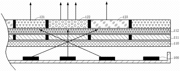
[0007] However, on the one hand, it is actually a general requirement of display technology to increase the display brightness. Especially when the resolution is continuously improved, the proportion of the display pixel area to the visible area is continuously reduced, resulting in a further decrease in display brightness. Therefore, in order to increase the display brightness, it is necessary to It is necessary to increase the proportion of the effective display area of ​​the LCD panel, and accordingly it is necessary to reduce the proportion of the black matrix between pixels as much as possible. In this way, the common practice in the industry is to improve the technology to reduce the size of the black matrix to improve the display brightness; on the other hand, the polarizer It is usually a composite film layer structure, and its thickness is generally greater than 100 microns. Generally, its thickness is further reduced by improving the preparation process and materials, but its improvement is extremely difficult.
Under normal circumstances, the width of the existing conventional BM region can reach 20 microns or less. Compared with the polarizer with known thickness in the existing liquid crystal display device, the BM region with the existing width can isolate the light from adjacent pixels The effect is limited. Even if the structural shape or manufacturing process of the polarizer is broken through to reduce its thickness, it is difficult to effectively solve the influence of the color crosstalk problem caused by the thickness of the polarizer.

Method used


Image

  • Liquid crystal display device
  • Liquid crystal display device
  • Liquid crystal display device

Examples


Embodiment Construction

[0029] The technical solutions in the embodiments of the present invention will be clearly and completely described below in conjunction with the accompanying drawings in the embodiments of the present invention. Obviously, the described embodiments are only part of the embodiments of the present invention, not all of them. Based on the embodiments of the present invention, all other embodiments obtained by persons of ordinary skill in the art without making creative efforts belong to the protection scope of the present invention.

[0030] In the description of the present invention, it should be understood that terms such as "upper", "lower", "horizontal", "vertical", etc. indicating orientation or positional relationship are based on the orientation or positional relationship shown in the accompanying drawings, and are only for It is convenient to describe the present invention and simplify the description, but not to indicate or imply that the device or element referred to m...


PUM


Abstract

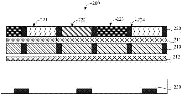
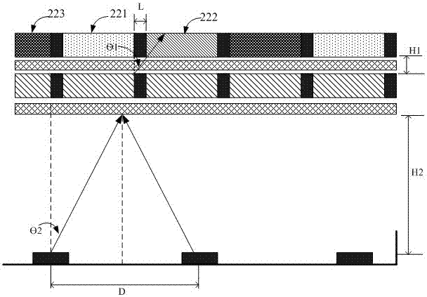
The invention provides a liquid crystal display device. The liquid crystal display device comprises a liquid crystal panel, wherein the liquid crystal panel comprises a quantum dot color pixel layer, an upper polarizer, a liquid crystal switch unit and a lower polarizer which are sequentially stacked; the quantum dot color pixel layer comprises a red sub-pixel unit, a green sub-pixel unit and a blue sub-pixel unit. The display device further comprises a backlight module arranged under the liquid crystal panel, the backlight module comprises a back plate and a light-emitting device arranged on the back plate, and the light-emitting device comprises an LED light-emitting device and an optical collimating device arranged above the LED light-emitting device. The optical collimating device is arranged above the LED light-emitting device according to the Lagrange-Helmholtz invariant, so that the light-emitting aperture is increased, then the light emitting angle of backlight is reduced, light rays can be collimated and emitted to a certain degree, and therefore the problem of color crosstalk between pixels due to large backlight emitting angles when the liquid crystal panel displays images is solved.

Description

technical field [0001] The invention relates to the field of display technology, in particular to a liquid crystal display device. Background technique [0002] In a new display method of LCD TV, the color filter of the traditional liquid crystal panel is directly replaced by the quantum dot color pixel layer, which mainly includes red sub-pixel unit, green sub-pixel unit and blue sub-pixel unit, among which the red sub-pixel The pixel unit is provided with red quantum dot material; the green sub-pixel unit is provided with green quantum dot material; the blue sub-pixel unit is provided with no quantum dot material or blue quantum dot material. When the blue backlight shines on the three pixel units of red, green and blue, the blue backlight in the blue sub-pixel unit directly transmits blue light; the quantum dot material in the green sub-pixel unit absorbs the blue light and converts it into green light, and the red light The quantum dot material in the sub-pixel unit abs...

Claims


Application Information

Patent Timeline
Patent Type & Authority Applications(China)
IPC IPC(8): G02F1/13357
CPCG02F1/133603G02F1/133606G02F1/133617G02F1/133607
Inventor 李富琳宋志成刘卫东
Owner HISENSE VISUAL TECH CO LTD
Why Eureka
Try Eureka