
relay

A relay and electric contact technology, applied in relays, electromagnetic relays, non-polar relays, etc., can solve problems such as electrical corrosion and cost increase, and achieve the effects of improving electrical corrosion resistance, improving environmental resistance, and suppressing leakage current

Active Publication Date: 2020-01-21
MITSUBISHI ELECTRIC CORP
View PDF9 Cites 0 Cited by
  • Summary
  • Abstract
  • Description
  • Claims
  • Application Information

AI Technical Summary

Problems solved by technology

[0010] In the relay disclosed in Patent Document 2, although the creepage distance between the main terminal and the parts forming the ground circuit is increased, there is a problem that other parts need to be assembled, resulting in an increase in cost
In addition, in the relay disclosed in Patent Document 2, the live line portion of the main terminal is exposed, and there is a problem that electrical corrosion is likely to occur in a water-immersed environment.

Method used


Image

  • relay
  • relay
  • relay

Examples


Embodiment approach 1

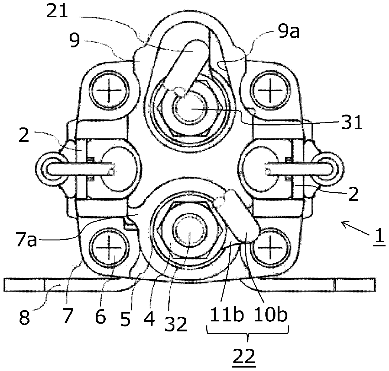
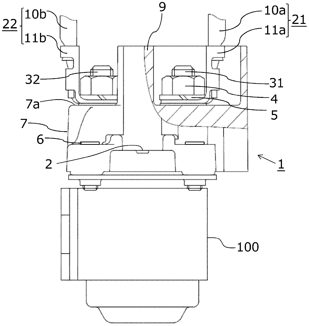
[0019] use figure 1 and figure 2 The relay 1 according to Embodiment 1 of the present invention will be described. figure 1 is the top view of relay 1, figure 2 is a sectional side view of the main part of the relay 1 . The above-mentioned relay 1 is, for example, a relay for switching on and off the current of the power supply system on the vehicle side.

[0020] Such as figure 1 As shown, in the relay 1 , main terminals 31 and 32 constituting a pair of main terminals are provided on the main surface portion side forming the front. The above-mentioned main terminals 31 and 32 are configured to be freely contactable and separated by electrical contacts (not shown) in the main body of the relay 1 . The above-mentioned electric contacts are driven by the excitation coil (not shown) in the main body of the relay 1, and as figure 1 As shown, an excitation terminal 2 connected to an excitation coil is provided on the main surface side of the relay 1 .

[0021] Here, the ma...

Embodiment approach 2

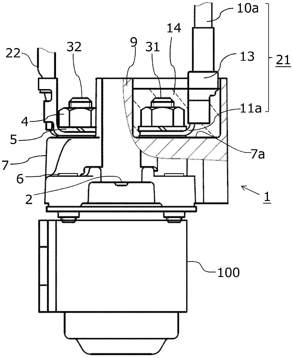
[0046] image 3 It is a cross-sectional side view of main parts of relay 1 according to Embodiment 2 of the present invention. In the relay 1 of the above-mentioned first embodiment, the case where the wiring 21 connected to the main terminal 31 is composed of the lead part 10a and the terminal part 11a connected to the end of the lead part 10a is exemplified, and the height of the partition wall part 9 is The height above the upper end of the terminal portion 11a. In Embodiment 2, the case where the wiring 21 constituting the relay 1 has a structure in which the insulating tube 13 is attached to the connecting portion between the connecting lead portion 10a and the terminal portion 11a will be described.

[0047] In the structure of the wiring 21, the terminal portion 11a fixed to the main terminal 31 is composed of a flat portion fastened by a nut 4 and connected to the main terminal 31, and a standing portion standing from the flat portion. and connected to the end of the...


PUM


Abstract

A relay can improve the electric corrosion resistance by only changing the shape of the cover of the relay without causing significant cost increase. A partition wall portion (9) that surrounds a main terminal (31) is integrally formed on a lid (7) that houses the electric contact of the relay (1) and is formed of a non-conductive member. With such a configuration, the partition wall portion (9) can be surrounded and protected against the main terminal (31), thereby improving environmental resistance. In addition, since the partition wall portion (9) is disposed between the conductive portions such as the main terminal (31) and the main terminal (32) forming the firewire, the creepage distance therebetween can be increased and the resistance to corrosion can be improved.

Description

technical field [0001] The present invention relates to a relay used for a starter or the like mounted on a vehicle. Background technique [0002] Generally, when starting a vehicle engine, in order to start the starter, a switch coil of the starter is energized. At this time, a large current is supplied from the vehicle-side power supply system to the starter switch. Therefore, instead of directly energizing the starter switch, a technique of energizing using a relay (starter relay) is employed. In the case of using a relay, a small current is passed from the vehicle side to the exciting coil of the relay to form a closed circuit of the electrical contact of the relay, thereby switching from the vehicle power supply to the starter via the electrical contact of the relay Coil energization. [0003] A relay is a structure with a pair of main terminals. Of the pair of main terminals, one main terminal is directly or indirectly connected to the vehicle-side power supply, an...

Claims


Application Information

Patent Timeline
Patent Type & Authority Patents(China)
IPC IPC(8): H01H50/14H01H50/44H01H51/06
CPCH01H50/14H01H50/443H01H51/065H01H50/02H01H2050/028
Inventor 山根康裕
Owner MITSUBISHI ELECTRIC CORP
Learn More