Electrical connector and inspection method of electrical connector

An electrical connector and inspection method technology, which is applied in the direction of electrical connection testing, parts and connections of connecting devices, etc., can solve problems such as difficulty in confirming the contact of grounding parts

Active Publication Date: 2020-11-03
HIROSE ELECTRIC GROUP
View PDF3 Cites 0 Cited by
  • Summary
  • Abstract
  • Description
  • Claims
  • Application Information

AI Technical Summary

Problems solved by technology

However, if the grounding member is provided inside the holding member, it is difficult to confirm whether the grounding member held by the holding member is in reliable contact with the ground terminal.

Method used


Image

  • Electrical connector and inspection method of electrical connector
  • Electrical connector and inspection method of electrical connector
  • Electrical connector and inspection method of electrical connector

Examples


no. 1 approach >

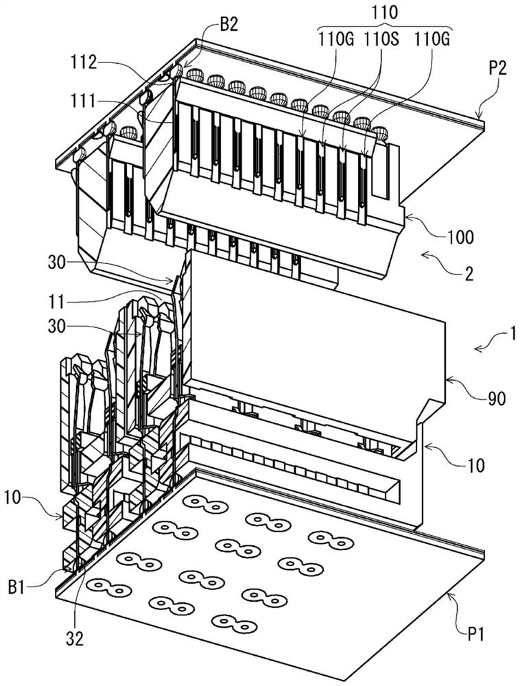
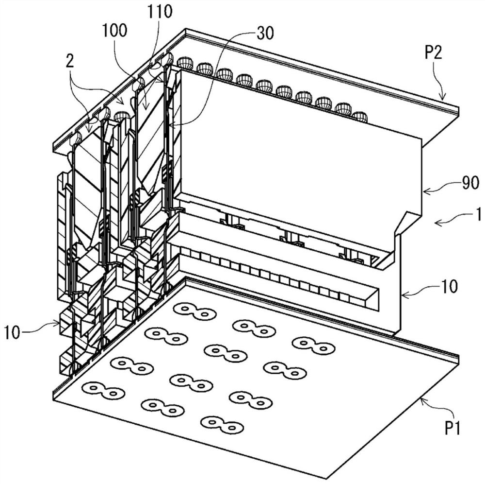
[0029] figure 1 It is a cross-sectional perspective view showing the electrical connector according to the first embodiment of the present invention together with a mating connector as seen from below, and shows a state before the connectors are fitted. in addition, figure 2 yes means figure 1 A cross-sectional perspective view of the mated connection state of the two connectors. The electrical connector 1 of the present embodiment (hereinafter simply referred to as "connector 1") is an electrical connector for a circuit board arranged on the mounting surface of the circuit board P1 as a component to be connected, and connects a plurality of objects from above. Connector 2. In addition, this object connector 2 is the electrical connector for circuit boards arrange|positioned on the mounting surface of another circuit board P2. In this embodiment, the connector 1 has a plurality of connection bodies 10 described later, and one connector 2 to be connected is connected to on...


PUM


Abstract

The present invention provides an electrical connector and an inspection method of the electrical connector which allow a grounding member to be in reliable contact with a grounding terminal and to easily confirm the state of electrical conduction between the grounding member and the grounding terminal. An electrical connector (1) is provided with: a plurality of terminals (30) having two types of terminals, a signal terminal (30S) and a ground terminal (30G); A holding body (50) made of an insulating material in which the terminals are arranged and held; and a grounding member (80) held by the holding body inside the holding body in a state of being in contact with at least two grounding terminals, and the grounding member has A detection unit (84) exposed from the holder for detecting a state of electrical conduction between the ground terminal and the ground member.

Description

technical field [0001] The present invention relates to an electrical connector with a grounding component and an inspection method of the electrical connector. Background technique [0002] As an electrical connector having a grounding member, for example, the electrical connector of Patent Document 1 is known. In the electrical connector of Patent Document 1, a plurality of plate-shaped blades in which a plurality of strip-shaped terminals (signal terminals and ground terminals) are arranged are arranged in a plurality in the thickness direction of the blades. The blades are integrally aligned and held by a plate-shaped base material made of an insulating material in a mixed state of signal terminals and ground terminals, and one end and the other end of each terminal are respectively connected to different mating connectors. In addition, a ground plate is attached to each plate surface of the base material of each blade so as to cover the terminal arrangement range, and ...

Claims


Application Information

Patent Timeline
Patent Type & Authority Patents(China)
IPC IPC(8): H01R13/40H01R13/502H01R13/648
CPCG01R31/54H01R13/40H01R13/502H01R13/648G01R31/69H01R12/73H01R13/6471H01R31/08G01R31/66H01R13/41
Inventor 奥山毅竹内洋介
Owner HIROSE ELECTRIC GROUP
Why Eureka
Try Eureka