
Braking device for small vehicle

A braking device and wheel brake technology, applied in the direction of bicycle brakes, bicycle accessories, etc., can solve the problems of increasing the variety of parts and narrow degrees of freedom, and achieve the effect of increasing the degree of freedom and reducing the variety of parts

Inactive Publication Date: 2008-01-09
HONDA MOTOR CO LTD
View PDF5 Cites 0 Cited by
  • Summary
  • Abstract
  • Description
  • Claims
  • Application Information

AI Technical Summary

Problems solved by technology

[0004] However, in the above-mentioned conventional devices, it is necessary to arrange additional parts such as interlocking links, which not only reduces the degree of freedom in arrangement, but also increases the variety of parts.

Method used


Image

  • Braking device for small vehicle
  • Braking device for small vehicle
  • Braking device for small vehicle

Examples


Embodiment Construction

[0028] Hereinafter, embodiments of the present invention will be described based on examples of the present invention shown in the attached drawings.

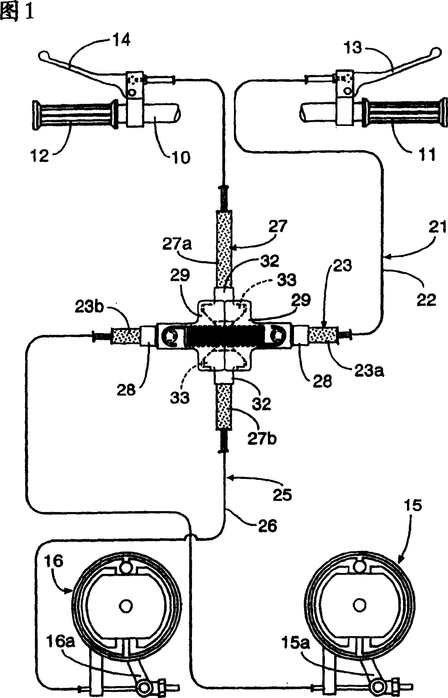
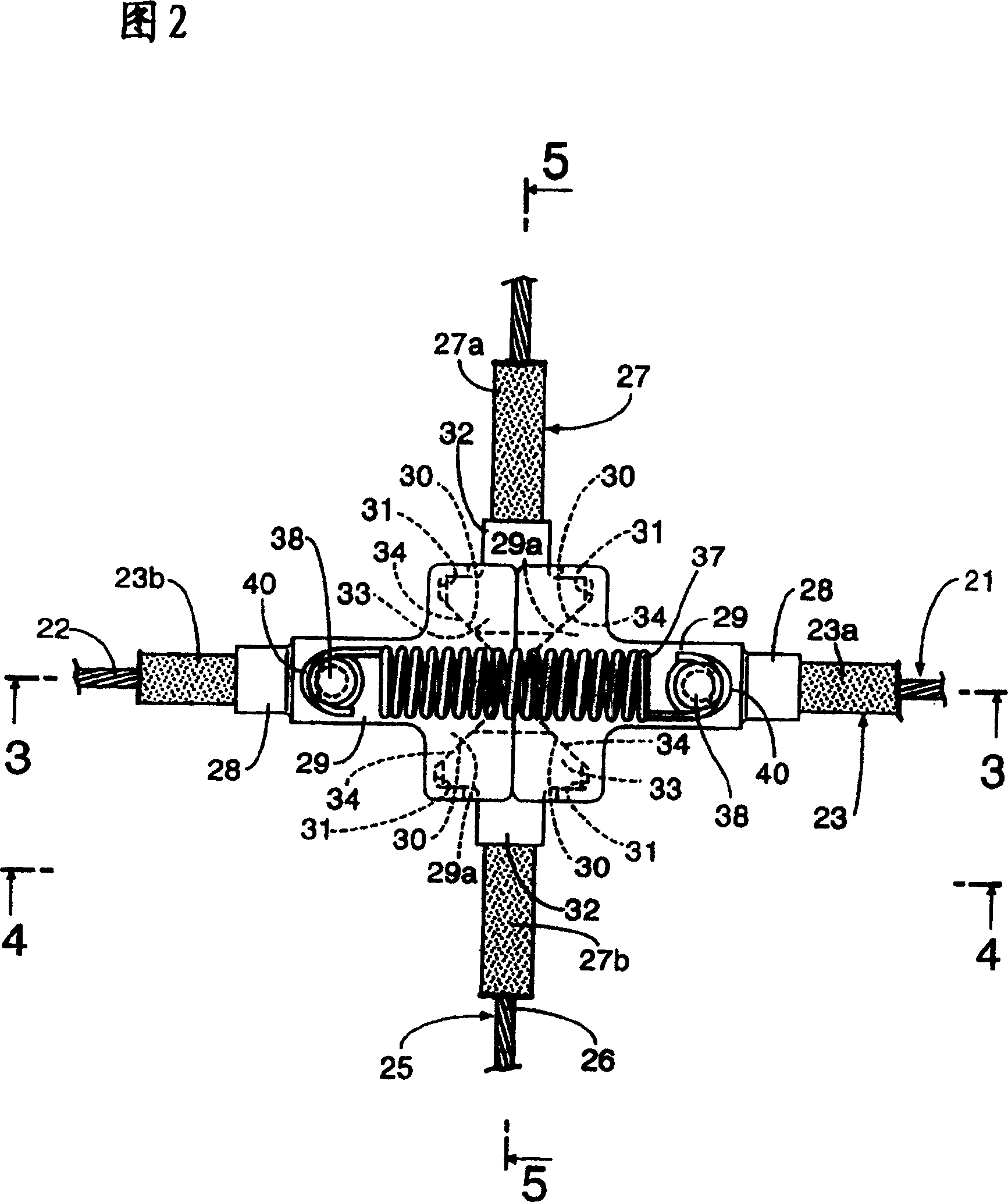
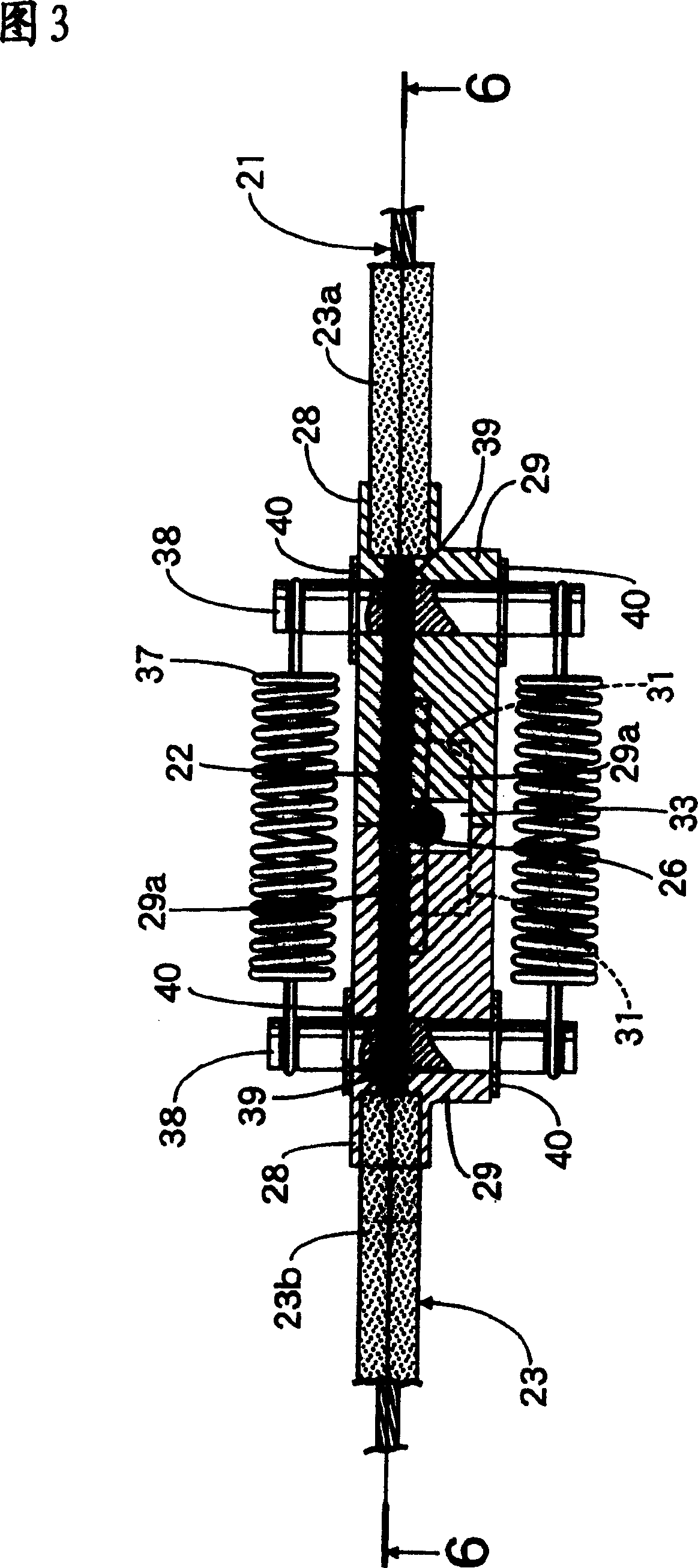
[0029] 1 to 7 show a first embodiment of the present invention. FIG. 1 is a diagram showing the structure of a motorcycle brake device. FIG. 2 is an enlarged view of the main parts of FIG. 1, and FIG. -3 line sectional view, Fig. 4 is a 4-4 line sectional view of Fig. 2, Fig. 5 is a 5-5 line sectional view of Fig. 2, Fig. 6 is a 6-6 line sectional view of Fig. The sectional view corresponding to Fig. 6 under the state of moving cable.

[0030] First, in FIG. 1, at the right end of the steering handle 10, the right handle 11 is installed, and at the same time, the right brake lever as the first brake operation member operated by the right hand that can hold the right handle 11 is pivotally supported. 13. In addition, a left handle 12 is attached to the left end of the steering handle 10, and a left brake lever 14, which is a s...


PUM


Abstract

To enhance flexibility on layout and reduce a number of parts by eliminating the need of disposing additional parts such as an interlocking link in a braking device for a small sized vehicle enabling the braking operation of one wheel brake even either of the two braking operation members is operated. A first outer cable of a first brake cable is divided into a first input side outer cable, and a second output side outer cable, and a pair of pressure receiving surfaces are formed on a pressure receiving part provided on an opposed end part of the first input side and first output side outer cables respectively. A pair of pressing parts with an inclined pressing surface so as to contact to the pressure receiving surface of the pressure receiving part on both sides respectively are provided so as to mutually move to close to each other according to towing operation of a second brake cable on a second brake cable 25 disposed so as to intersect with the first brake cable.

Description

technical field [0001] The present invention relates to a brake device for a small vehicle, and more particularly, to a brake device for a small vehicle that can cause one wheel brake to perform braking operation by operating any one of two brake operating members. Background technique [0002] There is a left and right pair of brake levers connected with the linkage link. The linkage link is connected with the front wheel brake and the rear wheel brake through individual brake cables. If any one of the two brake levers is operated, the front A device that performs a braking operation in conjunction with a wheel and a rear wheel brake (refer to Patent Document 1). [0003] [Patent Document 1] JP-A-2000-309294 [0004] However, in the above-mentioned conventional devices, it is necessary to arrange additional parts such as interlocking links, and not only the degree of freedom in arrangement is narrow, but also the variety of parts is increased. [0005] The present inventi...

Claims


Application Information

Patent Timeline
Patent Type & Authority Patents(China)
IPC IPC(8): B62L3/08B62L3/02
Inventor 冈崎泰典
Owner HONDA MOTOR CO LTD
Learn More