Small-module straight bevel gear forming method numerical control machining process

A technology of spur bevel gears and small modulus, which is applied in the field of CNC machining of small modulus spur bevel gears by forming method, can solve the problems of high flexibility, low cost, high efficiency processing requirements, low productivity, and high processing costs for changing types

Inactive Publication Date: 2014-10-01
河南平原光电有限公司
View PDF5 Cites 10 Cited by
  • Summary
  • Abstract
  • Description
  • Claims
  • Application Information

AI Technical Summary

Problems solved by technology

[0002] Small modulus straight bevel gears are the basic parts of the transmission mechanism, and are widely used in aerospace, weapons, instrumentation and other fields. Currently, the processing methods of small modulus straight bevel gears mainly include gear planing and double-cutter milling. method and round drawing method, among which the gear planing method mainly uses the cutting surface formed by two planers for reciprocating cutting motion to process the gear teeth. After one gear tooth is processed, the second gear tooth is processed until the machining The entire gear tooth, this method has very low productivity and is only suitable for small batches and single-piece production. The double-cutter milling method is to use the cutting surface formed by the rotation of two milling cutter discs to produce the shape of the gear teeth. After one gear tooth is processed, the second gear tooth is processed by indexing until the entire gear tooth is processed. This processing method is efficient, but the variety of tool changes leads to high processing costs. The circular drawing method is to ensure that the workpiece does not move. , while the broaching tool disc rotates, it reciprocates along the tooth direction to broach the tooth groove. However, this forming method can only be processed on a special machine tool, which has strong industry limitations. Therefore, the traditional processing method It can no longer meet the processing requirements of modern high flexibility, low cost and high efficiency

Method used


Image

  • Small-module straight bevel gear forming method numerical control machining process

Examples


Embodiment 1

[0028] Example 1: It is known that the gear modulus mo=1, the number of teeth Z=25, the pressure angle αe=20°, the axis angle Φ=90°, the dedendum height r1=1.25×mo, and the addendum height r2=1.0× mo, the measurement unit is millimeter mm;

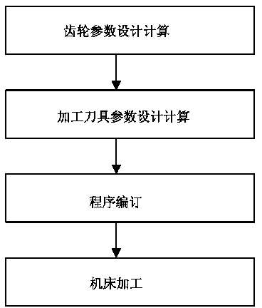
[0029] The first step: design and calculation of gear parameters, calculate and design the indexing angle of the gear according to the parameters such as the modulus mo of the gear to be produced, the number of teeth Z, the pressure angle αe, the included angle of the axis Φ, the height of the dedendum r1, and the height of the addendum r2 α, tip circle outer diameter φα, pitch circle outer diameter φa, cone generatrix length L, tooth length L1, small end modulus mi, pitch circle inner diameter φi, addendum angle δk, root cone angle δf and other parameters, the specific calculation method is as follows :

[0030] Indexing angle: α1=360° / Z=360° / 25=14.4

[0031] Top circle outer diameter: φα= mo×Z+2×cosδo=1.0×25+0.7071=26.41mm

[0032] Pi...


PUM


Abstract

The invention discloses a small-module straight bevel gear forming method numerical control machining process. The small-module straight bevel gear forming method numerical control machining process comprises the following steps of gear parameter design calculation, machining cutting tool parameter design calculation, program scheduling and machine tool machining. According to the small-module straight bevel gear forming method numerical control machining process, a tooth profile angle of a large end and a tooth profile angle of a small end are continuously modified through the angular displacement of a C axis of a numerical control gear hobbing machine and the axial displacement of a Y axis of the numerical control gear hobbing machine to obtain the tooth profile which is approximate to the spherical involute. The small-module straight bevel gear forming method numerical control machining process is less in cutting tool change type, high in machining efficiency and suitable for small batch production and mass production.

Description

technical field [0001] The invention relates to a process for machining small modulus straight bevel gears by numerical control forming method, which belongs to the field of gear machining process. Background technique [0002] Small modulus straight bevel gears are the basic parts of the transmission mechanism, and are widely used in aerospace, weapons, instrumentation and other fields. Currently, the processing methods of small modulus straight bevel gears mainly include gear planing and double-cutter milling. method and round drawing method, among which the gear planing method mainly uses the cutting surface formed by two planers for reciprocating cutting motion to process the gear teeth. After one gear tooth is processed, the second gear tooth is processed until the machining The entire gear tooth, this method has very low productivity and is only suitable for small batches and single-piece production. The double-cutter milling method is to use the cutting surface formed...

Claims


Application Information

Patent Timeline
Patent Type & Authority Applications(China)
IPC IPC(8): B23P15/14
CPCB23F5/20
Inventor 李忠叶培娟赵朝辉张小文牛鹏程
Owner 河南平原光电有限公司
Why Eureka
Try Eureka