Antenna connecting and switching device

A technology for connection switching and antennas, which is applied in the field of antenna connection switching devices, and can solve problems such as difficult positioning, pattern peeling, and elastic contact of power supply points that cannot be used for antennas.

Inactive Publication Date: 2013-12-18
SMK CO LTD
View PDF3 Cites 1 Cited by
  • Summary
  • Abstract
  • Description
  • Claims
  • Application Information

AI Technical Summary

Problems solved by technology

On the other hand, since the antenna connection terminal 103 receives a force from the planar antenna 110 mounted on the device side toward the direction of the printed wiring board 103, there is a normally closed terminal 102 integrated with the antenna connection terminal 103 toward the direction of the printed wiring board 103. Concerns about deflection, or detachment from the inner top surface of the mounted void 105a
[0012] In addition, if it is desired to fit and connect the coaxial plug 120 to the coaxial connector with switch 101 in an inclined posture, or to apply an external force in a direction other than the connection direction (vertical direction) to the coaxial plug 120 that is fitted and connected, Then, a rotational moment is generated in the coaxial connector 101 with a switch mounted on the printed circuit board 104, and a tensile stress is generated in the welding part of the power supply pattern 104a and the common terminal 107, so there is a possibility that the welding part is damaged or the pattern is peeled off. to worry about
[0013] In addition, since the strip-shaped antenna connection terminal 103 protrudes above the insulating case 105, it is easily plastically deformed by an unexpected external force, so that it cannot be correctly elastically contacted with the feeding point of the antenna.
In addition, in antennas other than the planar antenna 110 formed with the insertion hole through which the coaxial connector with switch 101 is inserted, the positioning of the elastic contact portion 103a with the antenna connection terminal 103 is difficult, and the elastic contact cannot be accurately made. The portion 103a comes into contact with the feeding point of the antenna, which causes deterioration of the transmission and reception signal characteristics of the antenna.

Method used


Image

  • Antenna connecting and switching device
  • Antenna connecting and switching device
  • Antenna connecting and switching device

Examples


Embodiment Construction

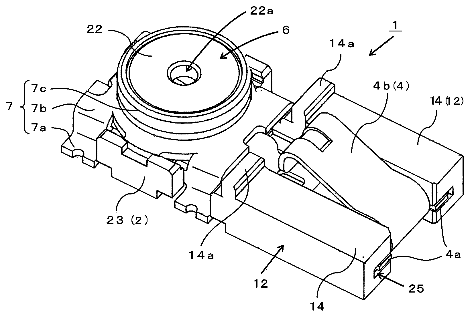
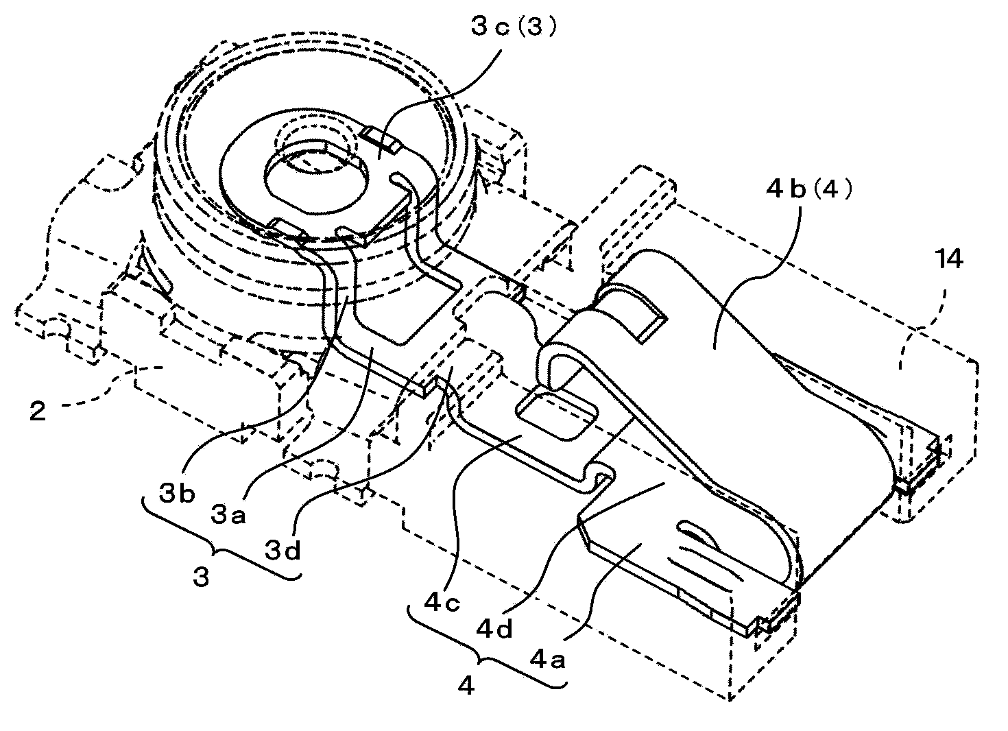
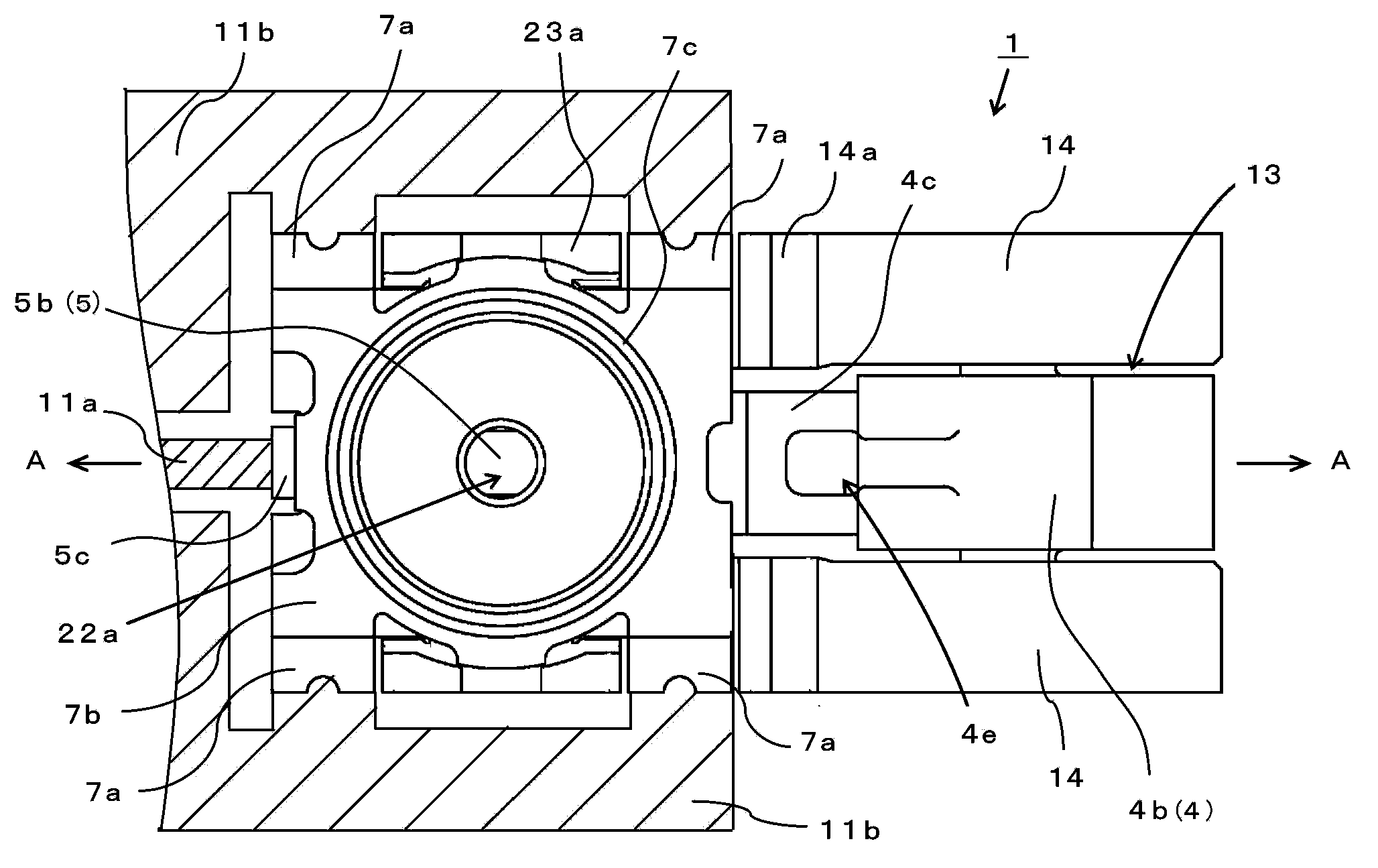
[0067] Below, use Figure 1 to Figure 10 Next, the antenna connection switching device 1 according to the first embodiment of the present invention will be described. Such as Figure 10 As shown in the circuit diagram, the antenna switch connection device 1 of this embodiment is connected to the general terminal 5 connected to the power supply circuit (not shown) between the normally closed terminal 3 connected to the antenna 10 and the center pin 21 of the coaxial plug 20 It is switched and connected, and has: a coaxial connector with a switch (hereinafter referred to as the coaxial connector) 6 with a normally closed terminal 3, a universal terminal 5 and a grounding shell 7 installed on the insulating housing 2; An antenna 10 ; an antenna connection terminal 4 connected to the antenna 10 ; and a printed wiring board 11 for surface mounting the coaxial connector 6 and the antenna connection terminal 4 .

[0068] For the printed wiring board 11, such as image 3 etc., on i...


PUM


Abstract

The invention provides an antenna connecting and switching device, which is capable of preventing the high-frequency signal flowing between the antenna and a supply circuit, and the welding connection between the antenna connecting and switching device and a printing and wiring substrate is not easy to be damaged. A universal terminal, a normally closed type terminal and an antenna connecting terminal are configured in that the projection of the printing and wiring substrate on the installing surface is continuously shown on the same line, with respect to a leg part welded to the universal terminal of the power supply image. The leg part of the antenna connecting terminal is welded to the welding disc image of the printing and wiring substrate at the separating position of the line. As no required inductance is generated at the transmitting path from the antenna to the power supply image, the high-frequency signal will not be reduced. Images connected to the printing and wiring substrate can be welded to the two separating positions of the line. Accordingly, even if the rotating torque in the same direction is generated, the welding connection part is not easy to be damaged.

Description

technical field [0001] The present invention relates to an antenna connection switching device for switching between an antenna power supply line and other transmission lines, and particularly relates to the following antenna connection switching device, that is, when a coaxial connector with a switch is fitted and connected to a coaxial plug, the The power supply circuit of the antenna is switched from the antenna to the external transmission line connected by the coaxial plug. Background technique [0002] In the case of outputting a high-frequency signal output from a power supply circuit in an electronic device to an antenna to an inspection circuit, or in the case of transmitting a high-frequency signal from another signal output system of an antenna to a power supply circuit in an electronic device, the A coaxial connector with a switch is arranged on the power supply line connecting the power supply circuit and the antenna, and the coaxial connector with a switch is f...

Claims


Application Information

Patent Timeline
IPC IPC(8): H01Q1/00H01Q1/50H01R24/46H01R24/50
Inventor 大塚亮富樫晃司
Owner SMK CO LTD
Why Eureka
Try Eureka