valve assembly

A valve component and valve module technology, applied in the direction of servo motor components, valve devices, valve details, etc., can solve the problem that the state information of a single valve module cannot be assigned to this valve module, and achieve the effect of easy reading

Active Publication Date: 2021-01-05
BURKERT WERKE
View PDF10 Cites 0 Cited by
  • Summary
  • Abstract
  • Description
  • Claims
  • Application Information

AI Technical Summary

Problems solved by technology

However, with this type of valve assembly it is not possible to assign status information of an individual valve module directly to this valve module in a simple form

Method used


Image

  • valve assembly
  • valve assembly
  • valve assembly

Examples


Embodiment Construction

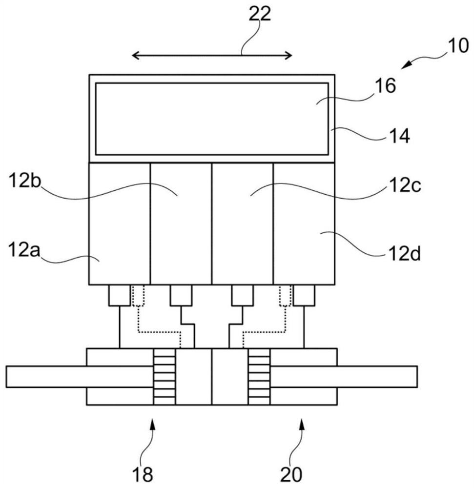
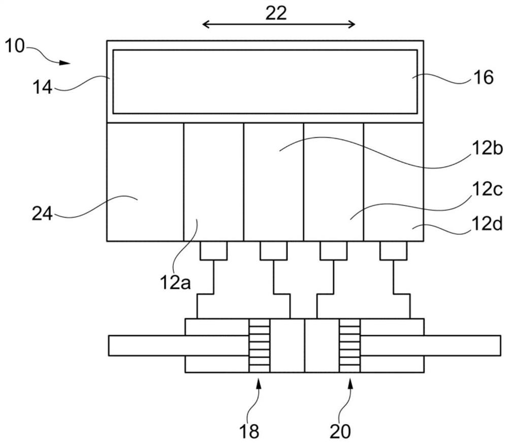
[0033] figure 1 A first embodiment of a valve assembly 10 comprising four valve modules 12a to 12d is shown.

[0034] Also arranged in the valve assembly 10 is a display module 14 in which a display device 16 in the form of a display is arranged.

[0035] A first part 18 in the form of an actuator (here a first pneumatic cylinder or a first pneumatic valve) is connected to the valve modules 12a and 12b, and a second part 20 in the form of a second actuator (here a pneumatic cylinder or a second pneumatic valve) are connected to the valve modules 12c and 12d so that each valve module has an integrated solenoid valve.

[0036] Typically, however, the valve module has two solenoid valves and thus two outputs to which eg pneumatic cylinders or pneumatic valves on opposite sides of the piston or actuating member are connected, i.e. one solenoid valve for ventilation and a solenoid valve for exhaust. The pneumatic valve is then closed by a spring and opened by air.

[0037] exis...


PUM


Abstract

The invention describes a valve assembly (10) having at least two valve modules (12a-12d), wherein the valve modules (12a-12d) are arranged side by side along a linear arrangement direction (22). The valve assembly (10) further comprises indicating means (16) for displaying the status of the valve modules (12a-12d) and / or the valve assembly (10) and / or components (18, 20) connected to the valve assembly. Along the alignment direction (22) the indicator device (16) extends continuously over all valve modules (12a-12d).

Description

technical field [0001] The invention relates to a valve assembly with at least two valve modules arranged next to each other in a linear alignment and with an indicator device for displaying the status of the valve modules and / or the valve assemblies and / or components connected to the valve assemblies. Background technique [0002] Such a valve assembly is known from DE 20 2013 011 331 U1. For example, a pneumatic cylinder can be connected to its valve module. On each valve module there is an indicator display, by means of which, for example, the functional state of the valve module or the actuator connected to the pneumatic cylinder can be indicated. The indicator display is designed, for example, as a colored signal lamp, wherein the color of the emitted light changes in the event of a change in the state of the monitoring function. The indicator displays are each arranged on an outer surface of the associated valve module. [0003] Another valve assembly of the aforeme...

Claims


Application Information

Patent Timeline
Patent Type & Authority Patents(China)
IPC IPC(8): F15B21/08F15B13/08
CPCF15B13/0825F15B13/0839F15B13/0857F15B13/0864F15B13/0867F15B13/0889F15B21/085F15B2211/3057Y10T137/8242Y10T137/7613Y10T137/87885F16K27/003Y10T137/6011Y10T137/4857F16K37/0025F16K37/0041F15B13/0817F15B13/0814F15B15/20F15B2215/30
Inventor 托马斯·哈姆托马斯·迪姆艾娜·施梅泽尔
Owner BURKERT WERKE
Why Eureka
Try Eureka