
Non-contact displacement measurement method and device based on spectral wavelength

A non-contact, displacement measurement technology, applied in the direction of measuring devices, optical devices, instruments, etc., can solve the problems of changing stability, measurement result influence, measurement error, etc.

Active Publication Date: 2017-12-22
GUANGDONG SAMSUN TECH CO LTD
View PDF7 Cites 8 Cited by
  • Summary
  • Abstract
  • Description
  • Claims
  • Application Information

AI Technical Summary

Problems solved by technology

However, there are some inherent defects in these two measurement principles, which are mainly reflected in two aspects: (1) There are requirements for the material of the measured object
The capacitive displacement sensor works like an electrode, and the measured object is like an opposite electrode [2], so the capacitive displacement sensor can only measure the measured object of conductive material; while the eddy current displacement sensor can only measure the metal material. Measurement
(2) Electromagnetic signals are susceptible to external interference
[0008] The problem with the existing non-contact displacement measurement methods and devices based on spectral wavelengths is: when certain points or faces on the measurement object are just processed by a certain monochromatic light, interference or reflection occurs, and the focus on the measurement object When the monochromatic light on the object cannot be reflected to the measuring device, measurement error will occur
This method can effectively solve this problem, but in actual use, the stability of the driving device that changes the distance between the optical element and the measurement object will have a certain impact on the measurement results

Method used

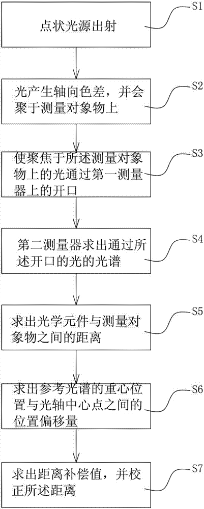
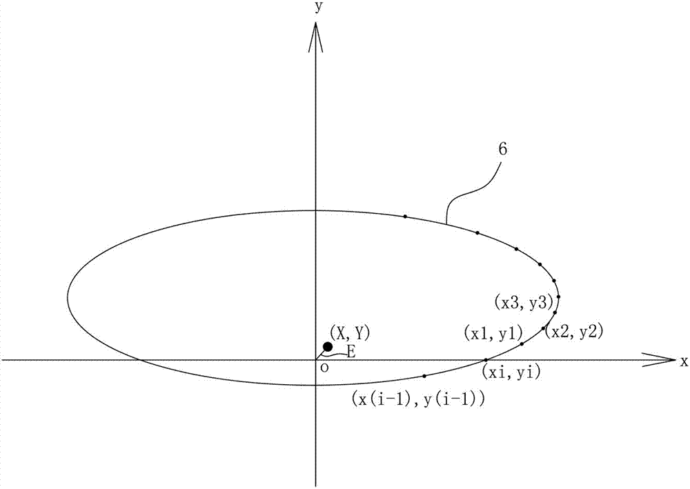
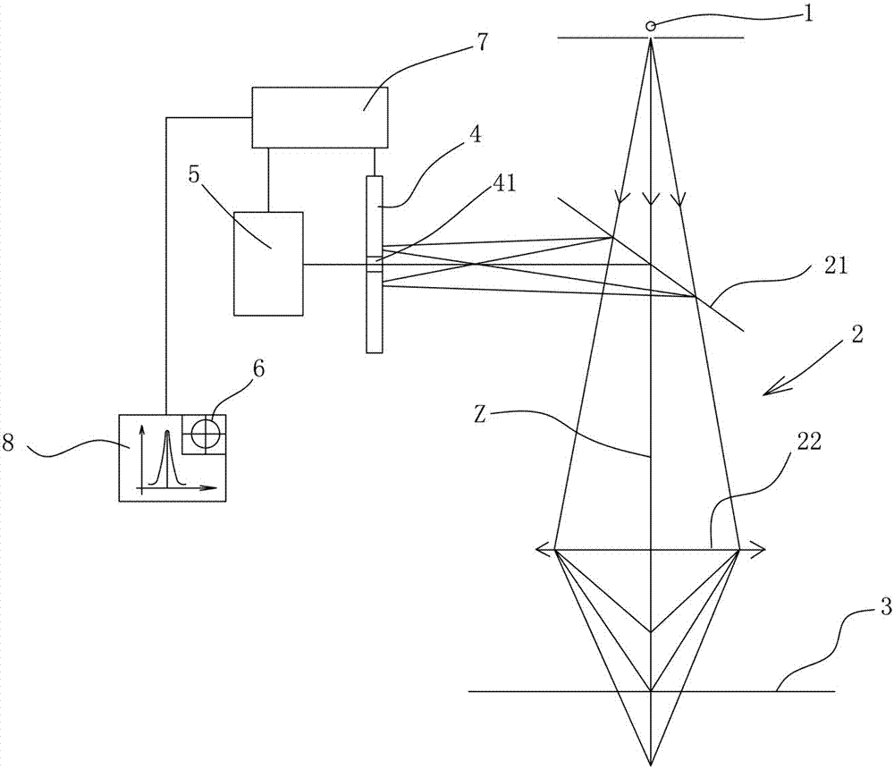

Image

  • Non-contact displacement measurement method and device based on spectral wavelength
  • Non-contact displacement measurement method and device based on spectral wavelength
  • Non-contact displacement measurement method and device based on spectral wavelength

Examples


Embodiment Construction

[0036] In the description of the present invention, it should be understood that the orientation or positional relationship indicated by the terms "center", "upper", "lower", "front", "rear", "left", "right" etc. are based on The orientations or positional relationships shown in the drawings are only for the convenience of describing the present invention and simplifying the description, and do not indicate or imply that the referred devices or components must have a specific orientation, be constructed and operated in a specific orientation, and therefore cannot be understood as Limitations on the Invention. In addition, the terms "first" and "second" are used for descriptive purposes only, and should not be understood as indicating or implying relative importance.

[0037] In the description of the present invention, it should be noted that unless otherwise specified and limited, the terms "installation", "connection" and "connection" should be understood in a broad sense, f...


PUM


Abstract

The invention relates to a non-contact displacement measurement method and device based on the spectral wavelength. The non-contact displacement measurement device comprises a point-shaped light source, an optical element, a first measuring appliance and a second measuring appliance, wherein the point-shaped light source emits multi-color light; the optical element enables the light to generate axial chromatic aberration and enables the light generating the axial chromatic aberration to be converged on a measurement object; the first measuring appliance is provided with an opening and enables the light focused on the measurement object in the light converged by the optical element to pass; the second measuring appliance solves the spectrum of the light passing through the opening and solves the distance between the optical element and the measurement object based on the peak wavelength of the spectrum; and the first measuring appliance solves the position offset between the center-of-gravity position of a light ring of a predetermined reference spectrum and an optical axis center point on the first measuring appliance and corrects the distance by using distance compensation value associated with the position offset. The non-contact displacement measurement device can also obtain a measurement result with high accuracy without changing the distance between the optical element and the measurement object.

Description

technical field [0001] The invention relates to a non-contact displacement measurement method based on spectral wavelength and a measurement device thereof. Background technique [0002] With the rapid development of precision and ultra-precision manufacturing, the requirements for displacement sensors are getting higher and higher: (1) Ultra-precision machining technology requires the accuracy of displacement sensors to reach submicron or even nanometer levels; (2) when the measured sample When the surface quality is high or it is a coated surface, the use of a contact displacement sensor may scratch the measured surface; when the measured sample is a weak rigid, light soft material (such as nylon, rubber), the macroscopic measurement force will make The elastic deformation of the contact point will have a certain influence on the measurement results. (3) The spindle speed of the machine tool in high-speed machining technology is as high as 10,000 revolutions, requiring th...

Claims


Application Information

Patent Timeline
IPC IPC(8): G01B11/00
CPCG01B11/002
Inventor 张庆祥唐小琦
Owner GUANGDONG SAMSUN TECH CO LTD
Learn More