Ultrasonic distance measuring device

A distance measuring device, ultrasonic technology, applied in the direction of measuring device, sound wave reradiation, radio wave measurement system, etc., can solve the problems of short measurement distance and unsatisfactory measurement distance, and achieve the effect of simple structure and improved driving power

Inactive Publication Date: 2014-03-19
CHERY AUTOMOBILE CO LTD
View PDF7 Cites 9 Cited by
  • Summary
  • Abstract
  • Description
  • Claims
  • Application Information

AI Technical Summary

Problems solved by technology

However, the existing ultrasonic distance measuring device can measure a short distance, generally only 2m to 3.5m. Although it can meet the needs of the existing vehicle reversing radar, it cannot meet the needs of other systems that require higher measurement distances.

Method used


Image

  • Ultrasonic distance measuring device
  • Ultrasonic distance measuring device
  • Ultrasonic distance measuring device

Examples


Embodiment 1

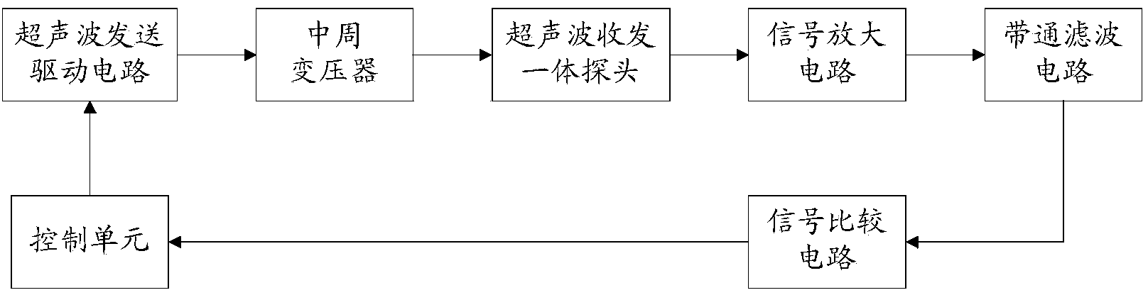
[0046] This embodiment provides an ultrasonic distance measuring device, such as figure 1 shown, which includes:

[0047] A control unit, an ultrasonic transmission drive circuit, a mid-period transformer, an ultrasonic transceiver integrated probe, a signal amplification circuit, a band-pass filter circuit and a signal comparison circuit.

[0048] The control unit is connected with the ultrasonic transmission driving circuit, and is used for outputting periodic pulse trains to the ultrasonic transmission driving circuit. The amplitude of the periodic pulse train is preferably around 5v.

[0049] Preferably, there are 20-30 pulses per train. The number of pulses is selected according to the actual debugging results of the ultrasonic distance measuring device described in this embodiment. Each series of pulses is 20-30, which can make the ultrasonic waves emitted by the ultrasonic transceiver integrated probe have the largest amplitude and the farthest propagation distance. ...

Embodiment 2

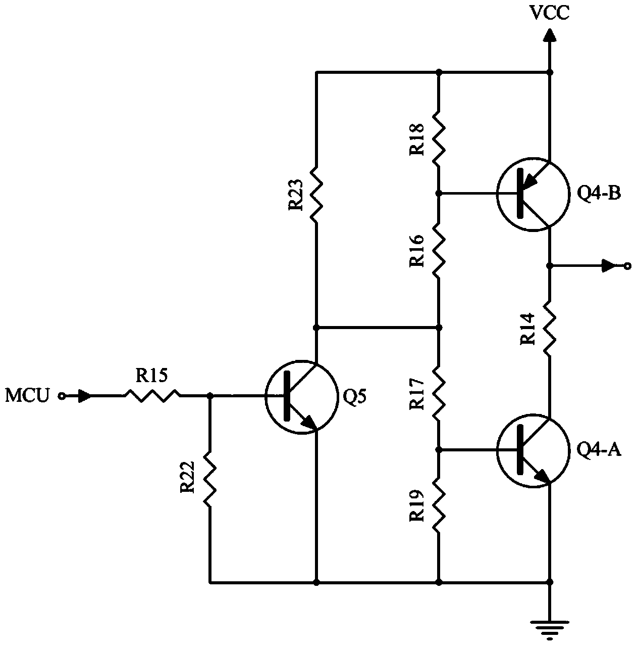
[0082] This embodiment provides an ultrasonic distance measuring device, such as Figure 7 shown, which includes:

[0083] The single-chip microcomputer is used to output periodic pulse trains, and obtains the measurement distance according to the periodic pulse trains output by it and the periodic pulse signals output by the signal comparison circuit;

[0084] Transistor Q5, triode Q4-A, triode Q4-B, resistor R14-resistor R19, resistor R22 and resistor R23, that is, the ultrasonic transmission drive circuit, is used to convert the periodic pulse train into a periodic sine wave signal;

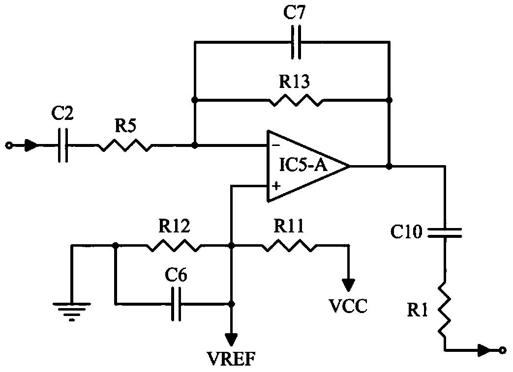
[0085] Capacitor C4 is used for AC coupling, which facilitates better amplification of the AC signal (that is, the periodic sine wave signal) output by the ultrasonic transmission drive circuit;

[0086] A mid-circumference transformer T1, used to boost the periodic sine wave signal;

[0087] The ultrasonic transceiver integrated probe UTS is used to transmit ultrasonic signals, receive ultr...


PUM


Abstract

The invention provides an ultrasonic distance measuring device. The ultrasonic distance measuring device comprises a control unit for outputting recurrent pulse strings, an ultrasonic wave transmitting and driving circuit for converting the recurrent pulse strings into recurrent sine wave signals, an intermediate frequency transformer for performing boosting processing on the recurrent sine wave signals, an ultrasonic transmitting-receiving integrated probe for transmitting ultrasonic signals to obstacles after being excited by the signals, receiving ultrasonic signals reflected by the obstacle and producing voltage signals corresponding to the reflected ultrasonic signals, a signal amplification circuit, a band-pass filtering circuit, a signal comparison circuit for converting filtered voltage signals into recurrent pulse signals, wherein the signal amplification circuit and the band-pass filtering circuit are respectively used for amplifying and filtering the voltage signal, and the control unit is further used for obtaining a measured distance according to output recurrent pulse strings and the recurrent pulse signals output by the signal comparison circuit. Compared with the prior art, the distance measured by the ultrasonic distance measuring device is large.

Description

technical field [0001] The invention relates to the technical field of ultrasonic ranging, in particular to an ultrasonic ranging device. Background technique [0002] Ultrasonic waves are often used for distance measurement due to their strong directivity, slow energy consumption, and long distances in the medium. The principle of ultrasonic ranging is: drive the ultrasonic transmitter to emit ultrasonic waves to obstacles, and start timing while emitting ultrasonic waves. When the ultrasonic waves encounter obstacles on the way to propagate, they will return immediately, and the returned ultrasonic waves (ie reflected waves) will be sent by the ultrasonic receiver. Receive, and stop timing when receiving the reflected wave, and calculate the distance between the transmitting point and the obstacle according to the propagation speed of the ultrasonic wave in the air and the recorded time difference. [0003] It is generally faster and more convenient to measure the distanc...

Claims


Application Information

Patent Timeline
Patent Type & Authority Applications(China)
IPC IPC(8): G01S15/08
CPCG01S15/101G01S15/102
Inventor 邓飞贺朱得亚
Owner CHERY AUTOMOBILE CO LTD
Why Eureka
Try Eureka