Volume pipe type multiphase flow metering device

A metering device, multiphase flow technology, applied in the direction of volume flow ratio measurement, measurement device, volume/mass flow generated by mechanical effects, etc., can solve the problems of low measurement accuracy, small measurement range, and inability to adapt to production changes in oil wells, etc. Achieve the effect of closed metering structure

Pending Publication Date: 2017-12-22
陈勇
View PDF10 Cites 0 Cited by
  • Summary
  • Abstract
  • Description
  • Claims
  • Application Information

AI Technical Summary

Problems solved by technology

[0006] The purpose of the present invention is to provide a volumetric tube type multiphase flow metering device, which is used to solve the problems in the prior art that the metering range is small, it cannot adapt to oil wells with large production changes, and the metering accuracy is low.

Method used


Image

  • Volume pipe type multiphase flow metering device
  • Volume pipe type multiphase flow metering device

Examples


Embodiment 1

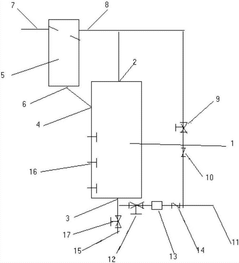
[0025] A volumetric tube type multiphase flow metering device, see figure 1 , the metering device comprises a metering tank 1, the top of the metering tank 1 is provided with a tank body gas outlet 2, the bottom of the metering tank 1 is provided with a tank body outlet 3, the top of the metering tank 1 is provided with a tank body liquid outlet 4, and the tank body liquid outlet 4 is connected with the pipeline liquid junction 6 of the metering pipeline 5, the upper part of the metering pipeline 5 is provided with a pipeline inlet 7 and a pipeline gas junction 8, the pipeline gas junction 8 is connected with the tank gas junction 2, and the pipeline gas junction 8 is connected with the tank gas junction. The junction 2 is connected to the gas path control valve 9, the first check valve 10, the gas flow meter and the metering outlet 11 in sequence, and the tank outlet 3 and the metering outlet 11 pass through the liquid path control valve 12, the water content meter 13 and the ...

Embodiment 2

[0032] A volumetric tube type multiphase flow metering device is similar to Embodiment 1, except that the number of capacitive liquid level switches 16 is three.

[0033] Preferably, the capacitive liquid level switches 16 are evenly distributed from top to bottom.

[0034] Preferably, the capacitive liquid level switch 16 includes two polar plates respectively.

[0035] Preferably, the distance between two pole plates of each capacitive liquid level switch 16 is at least 10 cm. In this way, it prevents the oil from sticking the two plates together to adapt to the high-viscosity medium. It adopts the capacitive wide plate liquid level switch, which can solve the problem that the high-viscosity medium sticks the floating ball and cannot be measured in the past.

Embodiment 3

[0037] A volumetric tube type multiphase flow metering device, which is similar to Embodiment 2, except that the water content meter 13 is a tube type water content analyzer.

[0038] Preferably, the moisture meter 13 is connected with a controller.


PUM


Abstract

The invention discloses a volume pipe type multiphase flow metering device. The top of a metering tank is provided with a tank body gas circuit port. The bottom of the metering tank is provided with a tank body outlet. An upper portion of the metering tank is provided with a tank body liquid circuit port. The tank body liquid circuit port is connected with a pipeline liquid circuit port of a metering pipeline. An upper portion of the metering pipeline is provided with a pipeline inlet and a pipeline gas circuit port. The pipeline gas circuit port is connected with the tank body gas circuit port. The pipeline gas circuit port and the tank body gas circuit port are both successively connected with a gas circuit control valve, a first check valve, a gas flow meter and a metering outlet. A liquid circuit control valve, a water content analyzer and a second check valve are successively connected between the tank body outlet and the metering outlet. The tank body outlet is connected with a sewage draining outlet. The pipeline inlet is of a reducing and inclined structure. Capacitive level switches are disposed in the metering tank. Wide range metering can be achieved, accurate metering for different gas flow sizes can be achieved, and the volume pipe type multiphase flow metering device is suitable for an oil well yield of which changes a lot. Metering is accurate and reliable due to an enclosed metering structure.

Description

technical field [0001] The invention relates to the technical field of oilfield equipment, in particular to a volume tube type multiphase flow metering device. Background technique [0002] At present, in oil well operations, it is often necessary to measure the total liquid volume, total gas volume, and oil volume and water volume produced every day. It is much more difficult to accurately measure multiphase flow than single-phase measurement. Single-phase metering can measure the flow rate by measuring the pressure, flow viscosity, compressibility and the geometric size of the measuring device. If the change of each phase is the same in the multi-phase flow, it is more convenient to handle, but more Phase metering is different from single-phase metering in the following aspects: (1) The phases are not mixed evenly. Water and oil do not mix well, and gas and liquid are separated; (2) Each phase flows at different speeds, and there are interface effects and relative speeds ...

Claims


Application Information

Patent Timeline
Patent Type & Authority Applications(China)
IPC IPC(8): G01F1/52G01F5/00
CPCG01F1/52G01F5/00
Inventor 陈勇
Owner 陈勇
Why Eureka
Try Eureka