A full-section flaw detection method and device for rail bottoms in service

A flaw detection device and full-section technology, which is applied in the field of flaw detection of in-service rails, can solve the problems of affecting the safety of rail transportation, failure to detect flaws, and long time consumption, etc., to achieve good flaw detection effects, stable and reliable flaw detection process, and ensure safety.

Active Publication Date: 2020-03-20
四川曜诚无损检测技术有限公司
View PDF6 Cites 0 Cited by
  • Summary
  • Abstract
  • Description
  • Claims
  • Application Information

AI Technical Summary

Problems solved by technology

[0003] Since the rail flaw detector probes of in-service rails are only arranged on the rail head tread, flaw detection can only be performed on the center of the rail bottom corresponding to the rail head, rail waist, and rail waist projection surface, and other parts of the rail bottom cannot be inspected Inspection, there are flaw detection blind spots, and furthermore, it is impossible to carry out flaw detection on the full section of the rail bottom in service, and the existence of rail bottom defects will seriously affect the safety of rail transportation; , it takes a long time, and due to artificial fatigue and instability, it will lead to poor quality of flaw detection, low efficiency, and even missed detection

Method used


Image

  • A full-section flaw detection method and device for rail bottoms in service
  • A full-section flaw detection method and device for rail bottoms in service
  • A full-section flaw detection method and device for rail bottoms in service

Examples


Embodiment 1

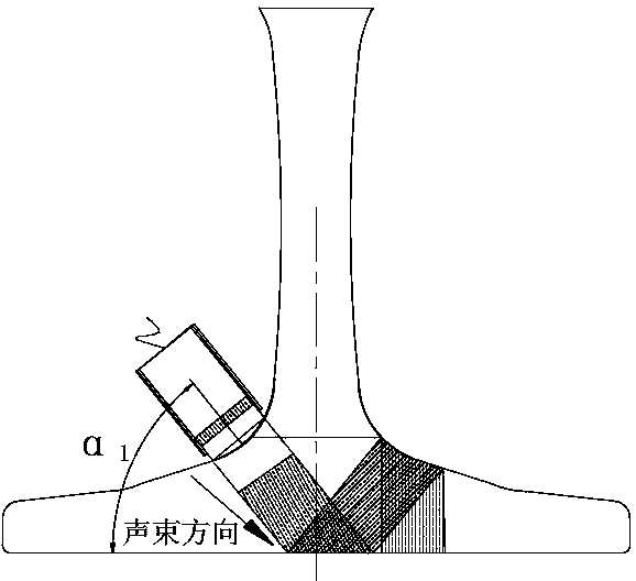
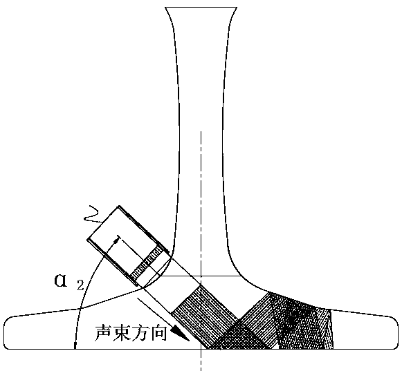
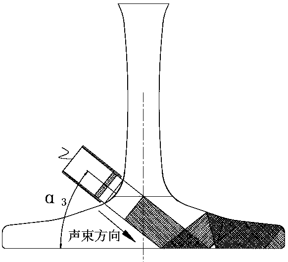
[0069] As shown in Figures 1 to 13 and 17, an in-service rail bottom full-section flaw detection device includes a trolley 1 and a flaw detection structure. The front and rear ends of the bottom of the trolley 1 are provided with track wheels 2, and the track wheels 2 are trolley 1 on the rail 3. The supporting rolling wheels on the tread surface play a supporting and guiding role for the trolley 1 to move forward on the rail 3. The flaw detection structure is set on the beam 4 at the bottom of the trolley 1 through the clamping mechanism. The flaw detection structure includes two sets of probes set on both sides of the rail 3 frame 5 and the probes 6 installed in the probe frame 5, when the flaw detection device is installed on the rail 3, the corresponding probes 6 in the two groups of probe frames 5 are symmetrical with respect to the central axis of the rail 3, and each set of probes includes at least three Each probe 6, the angle α between each probe 6 in a single group of...

Embodiment 2

[0074] Such as Figures 1 to 17 As shown, on the basis of Embodiment 1, the upper end of the probe frame 5 is fixedly connected with front and rear connecting rods 28,29, and the other ends of the front and rear connecting rods 28,29 are respectively equipped with front and rear landing gears 30,31. , The other ends of the rear landing gear 30, 31 are rotatably connected to the two ends of the same landing gear mounting seat 32, thereby realizing the closing and opening of the landing gear, making the loading and unloading of the flaw detection device faster and more convenient, and the front and rear connecting rods 28 , 29 are respectively adjustable in installation height on the front and rear landing gears 30, 31, and the landing gear mounting seat 32 is connected to the M-shaped connecting seat 14 bottom by the above-mentioned compensating rod 20, and the top of the above-mentioned arc waist-shaped hole 15 is all provided with Arcuate hole 33 is arranged, and the top of t...

Embodiment 3

[0079] Such as Figures 9 to 11, 17, on the basis of embodiment 2, the front end of the probe frame 5 (i.e. the forward end of the trolley 1) is provided with a rail 3 cleaning structure, and the rail 3 cleaning structure includes a motor 57, a steel brush head 58 and a motor holder 59, and the motor 57 is set on the front end of the probe frame 5 through the motor fixing seat 59, and the steel brush head 58 is connected to the end of the motor 57 through the coupling 60. 7, the arc zone 62 between 7, the motor 57 can automatically compensate and adjust downwards relative to the motor holder 59; it also includes a brush 63 arranged on the front end face of the probe frame 5, the brush 63 is positioned at the steel brush head 58 rear, the brush 63 Closely attached to the area to be tested; specifically, the motor 57 is connected to the motor fixing seat 59 through the motor mounting plate 64, the motor 57 is fixedly mounted on the front end of the motor mounting plate 64, and t...


PUM


Abstract

The invention relates to the technical field of flaw detection of in-service steel rails, and discloses a method and a device for carrying out flaw detection on the whole section of a rail bottom of an in-service steel rail. The device comprises a bogie and a flaw detection structure, wherein the flaw detection structure is arranged on a cross beam of the bogie by means of a clamping mechanism; the flaw detection structure comprises two groups of probe frames respectively arranged at the two sides of the steel rail, and probes installed in the probe frames; when the device used for carrying out flaw detection is installed on the steel rail, the probes which are correspondingly arranged in the two groups of probe frames are symmetrical relative to the steel rail; each group of probe includes at least three probes; the included angles alpha formed between all the probes in each group of probe and the bottom surface of the rail bottom of the steel rail are at least three different angle values and are within a range of 35-55 degrees; all the probes are perfectly jointed with a circular arc area between a rail waist of the steel rail and the steel bottom. According to the device, the probes at the two sides of the steel rails are closely jointed with the circular arc area between the rail waist and the steel bottom and respectively form the different included angles together with the plane of the rail bottom, so that the flaw detection for flaw detection blind areas of the rail bottom of the steel rail can be realized. The device and the method which are provided by the invention solve the problem of the flaw detection blind areas at present and guarantee the safety of rail transport.

Description

technical field [0001] The invention relates to the technical field of flaw detection of in-service rails, in particular to a full-section flaw detection method and device for rail bottoms of in-service rails. Background technique [0002] Rail flaw detection mainly uses ultrasonic waves for flaw detection, which can be divided into online flaw detection and line flaw detection according to the flaw detection location. On-line flaw detection is the use of automatic detection equipment on the production line by rail manufacturers to conduct ultrasonic flaw detection on rails. The probes are arranged on the rail head tread, the left and right sides of the rail head, the rail waist, and the rail bottom. The line flaw detection is mainly to use the rail flaw detection trolley to carry out ultrasonic flaw detection line flaw detection on the in-service rails laid on the line in the construction section of the Railway Bureau. The probe can only be placed on the rail head tread. ...

Claims


Application Information

Patent Timeline
Patent Type & Authority Patents(China)
IPC IPC(8): G01N29/04G01N29/265B61K9/10
CPCB61K9/10G01N29/048G01N29/265G01N2291/0234
Inventor 袁刚强童建明王泽斌赵世伟刘亚仑邓华幸嗣敏段宇李想黄学龙曾富周雪清刘长青刘志毅田慧磊张军郭超
Owner 四川曜诚无损检测技术有限公司
Why Eureka
Try Eureka