

Method and apparatus for establishing logical relationship between interested point and building, and server
A technology of logical relationship and points of interest, applied to devices and servers, a method of establishing a logical relationship between points of interest and buildings, which can solve the problem that the size of the building area cannot be accurately described and the scope of the building cannot be accurately displayed. and other problems to achieve the effect of saving labor costs
- Summary
- Abstract
- Description
- Claims
- Application Information
AI Technical Summary
Problems solved by technology
Method used
Image

Examples
Embodiment 1
[0086] Embodiment 1 The general process of establishing the logical relationship between POIs and buildings
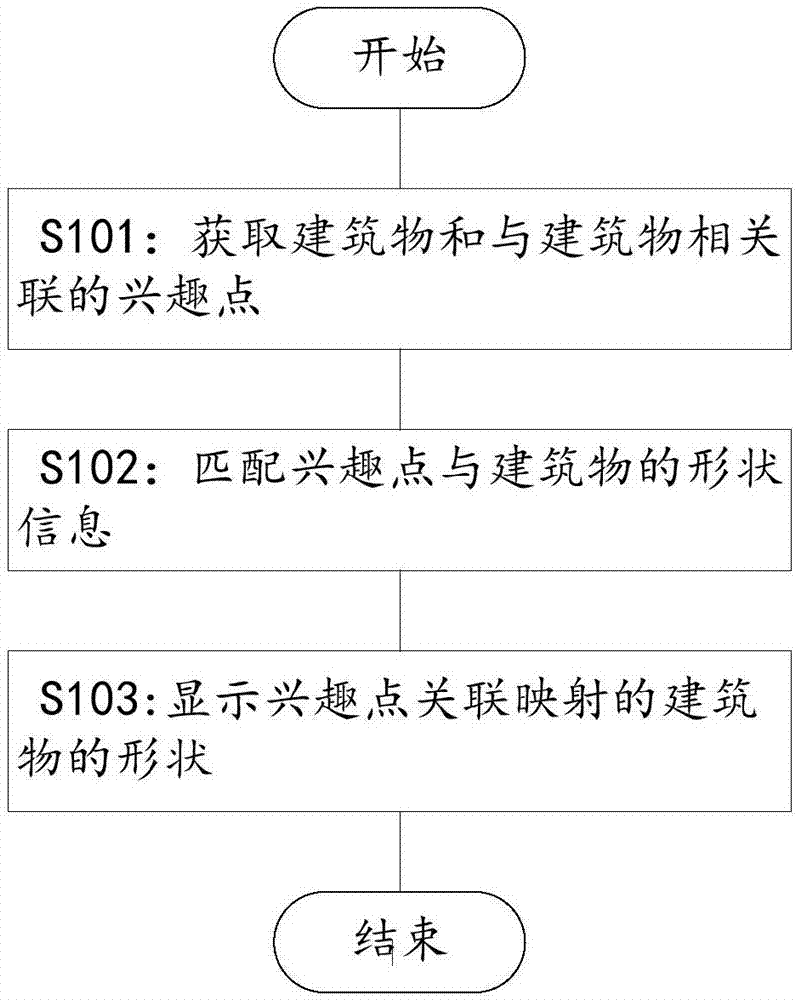
[0087] figure 1 It is a schematic flowchart showing a method for establishing a logical relationship between a point of interest and a building according to an embodiment of the present invention. Such as figure 1 As shown, according to an embodiment of the present invention, first in step S101, a building and a point of interest associated with the building are acquired, wherein the description information of the building includes shape information and geographic information of the building, and the point of interest The descriptive information includes the name and geographic coordinates of the POI. Wherein, the geographic information of the building refers to the geographic coordinates or address of the building, and the address refers to a spatial address or a communication address.
[0088] Buildings and points of interest can be obtained from the user terminal...
Embodiment 2
[0093] Embodiment 2 Based on the shape information of the building and the description information of the point of interest, a logical relationship between the point of interest and the building is established
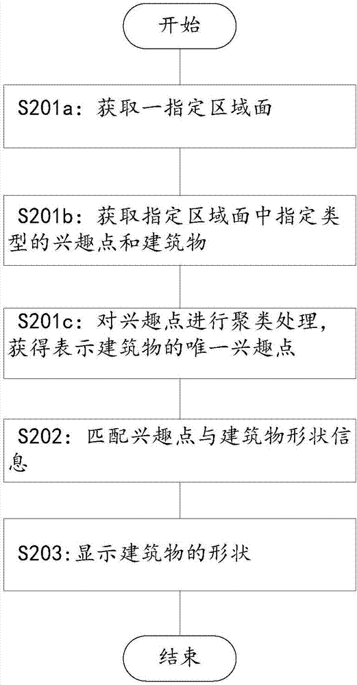
[0094] figure 2 is a schematic flow chart according to a specific embodiment of the present invention, Figure 3A and 3B based on figure 2 A schematic diagram of the user terminal interface during use of the embodiment. For clarity, only the figure 2 The example shown with the figure 1 Differences from the examples shown.
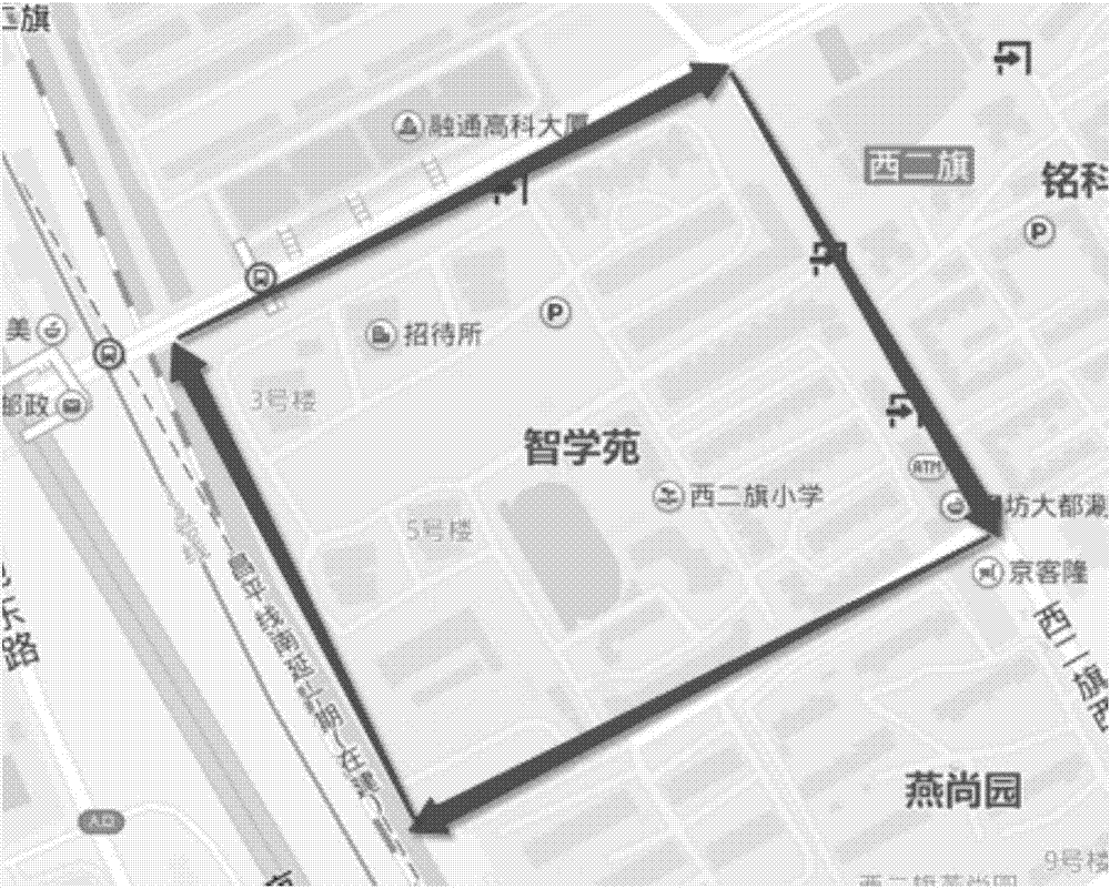
[0095] Such as figure 2 As shown, first in step S201a, a specified area surface is obtained. Here, the area plane can be obtained by methods known in the art such as keyword search method or box search method. Such as Figure 3A As shown, specify the area surrounded by the quadrilateral composed of arrows on the user interface "Zhixueyuan".
[0096] Then, in step S201b, at least a part of the POIs and buildings of the specified categor...
Embodiment 3
[0101] Embodiment 3 Based on the logical relationship between the known area surface and the interest point, the logical relationship between the interest point and the building is established
[0102] Figure 4 is a schematic flow chart according to yet another embodiment of the present invention; Figure 5A and 5B based on Figure 4 A schematic diagram of the user terminal interface during use of the embodiment. exist Figure 4In the illustrated embodiment, a logical relationship has been established between the specified area plane and the point of interest. In particular, there are a limited number of points of interest that the user is interested in in the specified area plane, for example, there is only one user interested in the specified area plane. points of interest. Generally, the specified area plane is an area plane of a cell-type POI, and this area plane is usually artificially created, and a mapping relationship with the POI has already been established. I...
PUM
 Abstract
Description
Claims
Application Information