
LED illumination lamp light modulation device and method

A technology of LED lighting and dimming device, applied in the field of LED lighting, can solve the problems of low power factor value, easy instability, sine wave interference signal, etc., and achieve the effect of simple use method

Active Publication Date: 2017-12-22
仪征元益光电科技有限公司
View PDF5 Cites 0 Cited by
  • Summary
  • Abstract
  • Description
  • Claims
  • Application Information

AI Technical Summary

Problems solved by technology

These three dimming methods, voltage control and PWM all require dedicated voltage regulating circuits and control lines. SCRs have advantages in application, but SCRs have many defects. 1. The waveform of the sine wave will be destroyed online Serious interference signals (EMI) are generated on the road; 2. It is easy to be unstable at low load, so a bleeder resistor must be added, and this bleeder resistor consumes at least 1-2 watts of power; 3. Power factor value Low, the smaller the conduction angle, the worse the power factor, even PF can be lower than 0.25

Method used


Image

  • LED illumination lamp light modulation device and method
  • LED illumination lamp light modulation device and method

Examples


Embodiment Construction

[0016] The present invention will be further described below in conjunction with the drawings and descriptions of the drawings.

[0017] The specific embodiments of the present invention will be further described below in conjunction with the accompanying drawings. It should be noted here that the descriptions of these embodiments are used to help understand the present invention, but are not intended to limit the present invention. In addition, the technical features involved in the various embodiments of the present invention described below may be combined with each other as long as they do not constitute a conflict with each other.

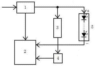
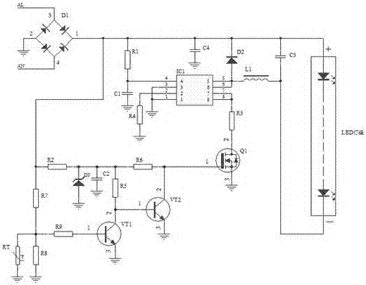
[0018] In this example, combined with figure 1 , a dimming device for LED lighting fixtures, comprising a rectifier circuit 1, a constant current drive circuit 2, a voltage detection circuit 3, a voltage-resistance converter 4, and an LED lamp group 5. The output end of the rectifier circuit 1 is electrically connected to the input end of th...


PUM


Abstract

The present invention relates to a light modulation mode of a LED illumination lamp. The light modulation device comprises a constant current driving circuit, a LED lamp set, a light modulation control circuit, a voltage and resistance convertor and a rectification circuit. The constant current driving circuit is electrically connected with the voltage and resistance convertor and the rectification circuit; the LED lamp set is electrically connected with the voltage and resistance convertor and the rectification circuit, the light modulation control circuit is electrically connected with the voltage and resistance convertor and the rectification circuit, and the voltage and resistance convertor is electrically connected with the constant current driving circuit, the LED lamp set and the light modulation control circuit. The LED illumination lamp light modulation device and method is scientific, advanced and reasonable, and the application method is simple. Compared to the current LED illumination lamp light modulation mode technology, general constant current drive IC is employed to allow the circuit to be simple and reliable, a special light modulation IC is not needed to realize light modulation of the LED illumination lamp, defects of a silicon controlled rectifier can be solved, and the product cost is reduced in the condition without influence of performances of the whole lamp.

Description

technical field [0001] The invention relates to a dimming device of an LED lighting fixture and a method thereof, belonging to the technical field of LED lighting. Background technique [0002] There are mainly three basic dimming methods of existing LED lighting fixtures, namely, 1 voltage control, 2 PWM, and 3 thyristor. These three dimming methods, voltage control and PWM all require dedicated voltage regulating circuits and control lines. SCRs have advantages in application, but SCRs have many defects. 1. The waveform of the sine wave will be destroyed online Serious interference signals (EMI) are generated on the road; 2. It is easy to be unstable at low load, so a bleeder resistor must be added, and this bleeder resistor consumes at least 1-2 watts of power; 3. Power factor value Low, the smaller the conduction angle, the worse the power factor, even PF can be lower than 0.25. Contents of the invention [0003] The object of the present invention is to provide a di...

Claims


Application Information

Patent Timeline
Patent Type & Authority Applications(China)
IPC IPC(8): H05B33/08H05B44/00
CPCH05B45/395H05B45/10
Inventor 赵协飞秦长平
Owner 仪征元益光电科技有限公司
Learn More