
Dismountable assembly push-assisting and pull-assisting device

A puller and component technology, which is applied to hand-held tools, manufacturing tools, etc., can solve the problems of inconvenient operation, inability to realize the push-pull function well, and achieve the effect of reducing weight and realizing light weight.

Inactive Publication Date: 2017-12-26
THE 724TH RES INST OF CHINA SHIPBUILDING IND
View PDF5 Cites 2 Cited by
  • Summary
  • Abstract
  • Description
  • Claims
  • Application Information

AI Technical Summary

Problems solved by technology

These structural methods are often inconvenient to operate, and cannot well realize the function of boosting and pulling out

Method used


Image

  • Dismountable assembly push-assisting and pull-assisting device
  • Dismountable assembly push-assisting and pull-assisting device
  • Dismountable assembly push-assisting and pull-assisting device

Examples


Embodiment Construction

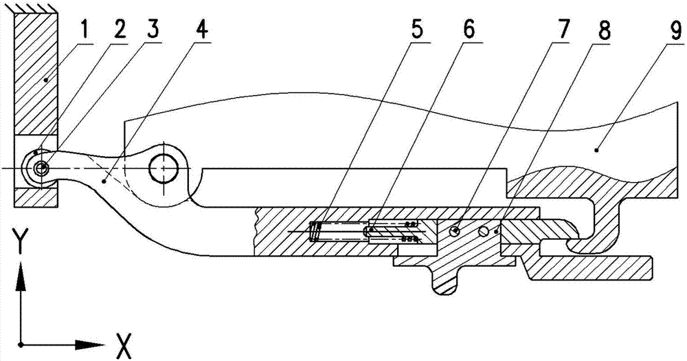
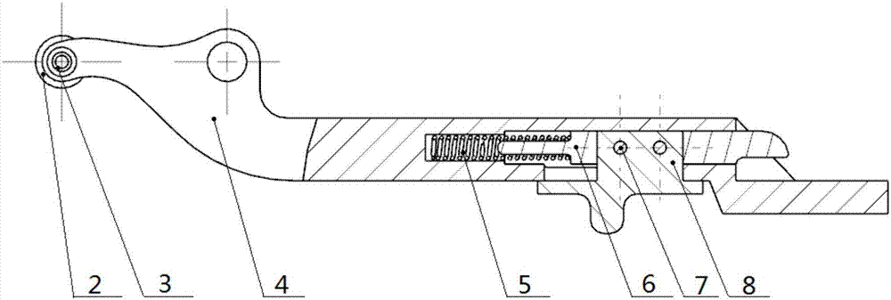
[0016] A detachable component booster and puller disclosed by the present invention includes a fixed base, a handle, and a component. The handle is connected with a roller, a card pin, and a pusher. The handle and the roller are riveted together by a bolt to form a rotating pair. The card pin and the pusher are riveted together through the latch, and there is a guide groove inside the handle for placing the spring and the card pin, and the card pin establishes a mobile pair connection relationship with the handle through the spring. The component can only move along the direction of the guide rail through the restriction of an external sliding guide rail. The component has a hook-shaped structure that cooperates with the card pin and locks, and a cylindrical boss that matches the through hole on the handle. The base is fixed, and there are grooves inside it that interact with the rollers.

[0017] In order to more clearly illustrate the specific solutions of the embodiments of...


PUM


Abstract

The invention discloses a dismountable assembly push-assisting and pull-assisting device. The dismountable assembly push-assisting and pull-assisting device comprises a fixed base 1, a handle 4 and an assembly 9 with a hook-shaped structure. A roller 2, a clamping needle 6 and a pusher 8 are connected to the handle 4, the handle 4 is in rivet connection with the roller 2 through a plug pin 3 to form a rotation pair, the clamping needle 6 is in rivet connection with the pusher 8 through a plug pin 7, a guide groove used for storing a spring 5 and the clamping needle 6 is formed in the handle 4, and the clamping needle 6 and the handle 4 build a sliding pair connection relation through the spring 5. A hook-shaped structure matched with the clamping needle 6 for locking is arranged on the position, on the right side of a picture, of the assembly 9, and a cylindrical boss matched with a through hole formed in the handle 4 is arranged on the left side of the picture of the assembly 9. The base 1 is fixed, and a groove interacting with the roller 2 is formed in the base 1. According to the dismountable assembly push-assisting and pull-assisting device, the structure is relatively simple, operation is convenient, and the dismountable, push-assisting and pull-assisting functions can be effectively achieved.

Description

technical field [0001] The invention belongs to the field of mechanical structure and mechanical design. Background technique [0002] In the actual application of engineering, general electronic components often need to be debugged in the early stage of development, which may lead to repeated plugging and unplugging of components. In the case of relatively large resistance to plugging and unplugging of components and repeated plugging and unplugging, it will bring great inconvenience to the debugging of new products. [0003] In current engineering applications, in order to solve this problem, there are already many solutions to solve the problem of plugging and unplugging the above-mentioned components. Some of these methods adopt the method of installing a fixed boosting and pulling-out structural device on the component to realize the boosting and pulling-out of the component. This fixed component form often increases the complexity of the product structure, and will o...

Claims


Application Information

Patent Timeline
Patent Type & Authority Applications(China)
IPC IPC(8): B25B27/00B25B27/02
CPCB25B27/00B25B27/02
Inventor 晏腾飞项立银李谦
Owner THE 724TH RES INST OF CHINA SHIPBUILDING IND
Learn More