Eureka AIR delivers breakthrough ideas for toughest innovation challenges, trusted by R&D personnel around the world.

Aerial camera with professional tripod

A technology of aerial photography device and tripod, which is applied in the field of aerial photography device, can solve the problems of aerial photography device damage, aerial photography device without shock-absorbing tripod, etc., and achieve the effects of prolonging service life, improving shooting quality and shooting efficiency, and ensuring stability

Inactive Publication Date: 2017-12-26
成都鑫晨航空科技有限公司
View PDF0 Cites 1 Cited by
  • Summary
  • Abstract
  • Description
  • Claims
  • Application Information

AI Technical Summary

Problems solved by technology

[0003] The invention provides an aerial photography device with a professional tripod, which solves the problem that the aerial photography device in the prior art does not have a shock-absorbing tripod, and it is easy to cause damage to the aerial photography device due to improper landing.

Method used


Image

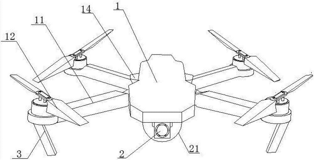
  • Aerial camera with professional tripod
  • Aerial camera with professional tripod
  • Aerial camera with professional tripod

Examples


Embodiment 1

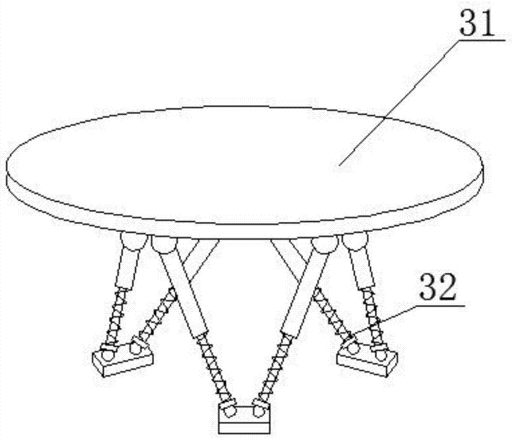
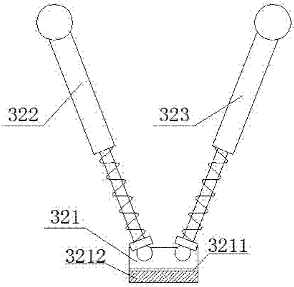
[0027] like Figure 1-Figure 4 As shown, an aerial camera with a professional tripod includes an aerial camera body 1 and a camera 2 arranged at the bottom of the aerial camera body 1. The aerial camera body 1 is provided with a plurality of sets of wings 11 with propellers 12, so The bottom of one end of the wing 11 is provided with a shock absorbing device 3, the shock absorbing device 3 includes a connecting plate 31 and a shock absorbing leg 32, the connecting plate 31 is connected to the bottom of the wing 11, and the shock absorbing leg 32 includes Three sets of adjustment assemblies distributed along the circumference of the connecting plate, the adjustment assemblies include a base 321 on which a left telescopic rod 322 and a right telescopic rod 323 are hinged, and the left telescopic rod 322 and the right telescopic rod 323 form a V The other ends of the left telescopic rod 322 and the right telescopic rod 323 are both hinged to the connecting plate 31 .

Embodiment 2

[0029] On the basis of Embodiment 1, the left telescopic rod 322 and the right telescopic rod 323 both include a lower spherical hinge 324 hinged on the base 321 , and a limiting disk 325 is connected to the lower spherical hinge 324 , and the limiting disk 325 is connected with a telescopic rod 326, the other end of the telescopic rod 326 is connected with an upper spherical hinge 327, the upper spherical hinge 327 is hinged with the connecting plate 31, and a shock-absorbing spring 328 is also sleeved on the telescopic rod 326, so One end of the shock-absorbing spring 328 is connected to the limit plate 325 , and the other end of the shock-absorbing spring 328 is connected to the telescopic rod 326 .

Embodiment 3

[0031] On the basis of Embodiment 1 or 2, the base 321 includes a connection layer 3211 and a shock absorption layer 3212, the left telescopic rod 322 and the right telescopic rod 323 are both hinged on the connection layer 3211, and the shock absorption layer 3212 is Rubber mat.


PUM


Abstract

The invention discloses an aerial camera with a professional tripod. The aerial camera comprises an aerial camera main body and a camera arranged at the bottom of the aerial camera main body, wherein multiple sets of wings with propellers are arranged on the aerial camera main body; a damping device is arranged at the bottom at one end of the wings; the damping device comprises a connecting plate and a damping tripod; the connecting plate is connected with the bottom of the wings; the damping tripod comprises three sets of adjusting components which are distributed along the peripheral direction of the connecting plate; each adjusting component comprises a base; a left expansion link and a right expansion link are hinged on the base; the left expansion link and the right expansion link are arranged in V shape; and the other ends of the left expansion link and the right expansion link are both hinged with the connecting plate. According to the invention, the damping device is arranged, the V-shaped damping tripod is arranged and a triangular structure is formed between the damping tripod and the connecting plate, so that the damping and stabilizing functions are achieved and the safe landing of the aerial camera is guaranteed.

Description

technical field [0001] The invention relates to the field of aerial cameras, in particular to an aerial camera with a professional tripod. Background technique [0002] Aerial photography, also known as aerial photography or aerial photography, refers to photographing the earth's landforms from the air to obtain a top-down view, which is an aerial photo. At present, most aerial photography is to install the camera on the aerial camera, and to capture the desired image by controlling the flight route of the aerial camera. Aerial cameras have been well used in many places, such as water conservancy and hydrology observation, TV program recording, etc., and even in some important celebrations. When you need to choose soft terrain, improper landing will easily cause the problem of damage to the aerial camera. SUMMARY OF THE INVENTION [0003] The present invention provides an aerial camera with a professional tripod, which solves the problem that the aerial camera in the pri...

Claims


Application Information

Patent Timeline
Patent Type & Authority Applications(China)
IPC IPC(8): B64C25/62B64C27/08B64D47/08
CPCB64C25/62B64C27/08B64D47/08B64U10/10B64U2101/30
Inventor 石存岭
Owner 成都鑫晨航空科技有限公司
Why Eureka
Eureka Blog
Learn More