Fertilization device capable of realizing unilateral and bilateral switching fertilization

A technology of fertilization device and fertilization vehicle, which is applied in the direction of fertilization device, fertilizer distributor, agricultural gas emission reduction, etc. It can solve the problems of unfavorable mechanical fertilization, unreasonable design, uneven fertilization, etc., and achieve the effect of improving the efficiency of fertilization

Inactive Publication Date: 2017-12-29
毛林杰
View PDF5 Cites 3 Cited by
  • Summary
  • Abstract
  • Description
  • Claims
  • Application Information

AI Technical Summary

Problems solved by technology

In the process of artificial fertilization, uneven fertilization often occurs. Due to the unreasonable design of the existing fertilization devices on the market, fertilization can only be performed on one side, and the fertilization efficiency is slow and cannot be adjusted according to actual needs. Solid chemical fertilizers often have agglomeration problems in weather, which brings many difficulties to storage, transportation and use. Serious agglomeration of chemical fertilizers is difficult to break, and chemical fertilizer agglomeration is not good for mechanical fertilization. Fertilizers are not easy to discharge and may cause blockage of fertilization ports. These It will bring inconvenience to fertilization and cannot meet the existing needs of fast and efficient fertilization

Method used


Image

  • Fertilization device capable of realizing unilateral and bilateral switching fertilization
  • Fertilization device capable of realizing unilateral and bilateral switching fertilization
  • Fertilization device capable of realizing unilateral and bilateral switching fertilization

Examples


Embodiment Construction

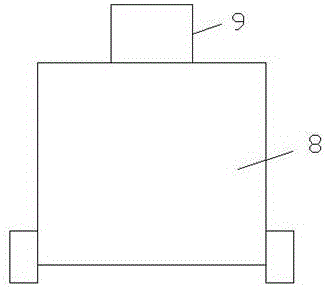
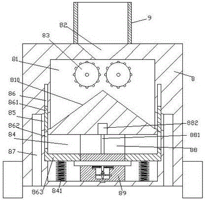
[0021] Such as Figure 1-Figure 9 As shown, a fertilization device capable of switching fertilization on both sides of the present invention includes a fertilization car body 8 and a feeding box 9 installed on the top of the fertilization car body 8, and the inner wall of the fertilization car body 8 is provided with a crushing chamber 81 The inner top wall of the crushing chamber 81 is provided with a funnel chamber 82 connected to the bottom of the feeding box 9, and the left and right sides of the crushing chamber 81 below the bottom of the funnel chamber 82 are symmetrically provided with rotating crushing chambers. mechanism 83, a guide slope 810 is fixed on the inner bottom wall of the crushing chamber 81 below the rotating crushing mechanism 83, and a first sliding chamber 84 is provided in the fertilization vehicle body 8 at the bottom of the crushing chamber 81, A guide cavity 88 is provided in the inner wall of the rear side of the first sliding cavity 84, and a disc...


PUM


Abstract

The invention discloses a fertilization device capable of realizing unilateral and bilateral switching fertilization. The fertilization device comprises a fertilization vehicle and a feeding box mounted at the top of the fertilization vehicle, wherein a crushing cavity is formed in the inner wall of the fertilization vehicle, a hopper cavity communicated with the bottom of the feeding box penetrates through the inner top wall of the crushing cavity, rotary crushing mechanisms are symmetrically arranged on left and right sides in the crushing cavity below the bottom of the hopper cavity, a guide slope part is fixedly arranged on the inner bottom wall of the crushing cavity below the rotary crushing mechanisms, a first sliding cavity is formed in the fertilization vehicle at the bottom of the crushing cavity, a guide cavity is formed in the inner wall of the back side of the first sliding cavity, discharging channels extending vertically are formed in the fertilization vehicle on left and right sides of the first sliding cavity, top extension tips of the discharging channels on the left and right sides extend to opposite positions of left and right sides of the bottom of the crushing cavity respectively. The fertilization device is simple in structure and convenient to operate, the fertilization efficiency is improved, the labor force is reduced, the workload of workers is reduced, and the working efficiency is improved.

Description

technical field [0001] The invention relates to the technical field of agricultural machinery, in particular to a fertilization device capable of switching between single and double sides for fertilization. Background technique [0002] Crops need to be fertilized during the growth period to ensure that the crops grow well. The traditional fertilization method is artificial fertilization. At present, my country's fertilization technology is not high, and there is a lack of effective and suitable fertilization devices. In the process of manual fertilization, uneven fertilization often occurs. Due to the unreasonable design of the existing fertilization devices on the market, fertilization can only be performed on one side. The fertilization efficiency is slow and cannot be adjusted according to actual needs. Solid chemical fertilizers often have agglomeration problems in weather, which brings many difficulties to storage, transportation and use. Serious agglomeration of che...

Claims


Application Information

Patent Timeline
Patent Type & Authority Applications(China)
IPC IPC(8): A01C15/12A01C15/00A01C19/02
CPCA01C15/003A01C15/12A01C19/02Y02P60/21
Inventor 毛林杰
Owner 毛林杰
Why Eureka
Try Eureka