Al technical title is built by PatSnap Al team. It summarizes the technical point description of the patent document.
A robotic and automatic technology, applied in metal processing and other directions, can solve problems such as low efficiency and waste of manpower, and achieve the effect of convenient placement and retrieval, smoothness and correctness, and accuracy.
Inactive Publication Date: 2019-05-07
HEFEI ZHIHUI LONGTUTENG INTPROP CO LTD
View PDF7 Cites 0 Cited by
Summary
Abstract
Description
Claims
Application Information
AI Technical Summary
This helps you quickly interpret patents by identifying the three key elements:
Problems solved by technology
Method used
Benefits of technology
Problems solved by technology
[0002] After the photo is printed, there will be a white blank area around it. This area needs to be cut out. The current cutting method is to cut with a paper cutter or scissors. Each photo needs to be cut out one by one by hand. , this cutting method wastes manpower and is inefficient
Method used
Image
Click on the blue label to locate the original text in one second.
Reading with bidirectional positioning of images and text.
Examples
Embodiment Construction
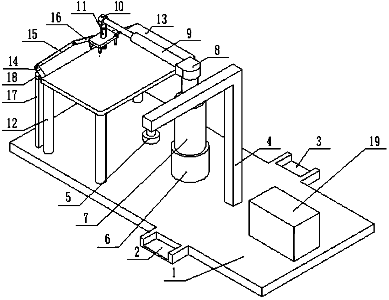
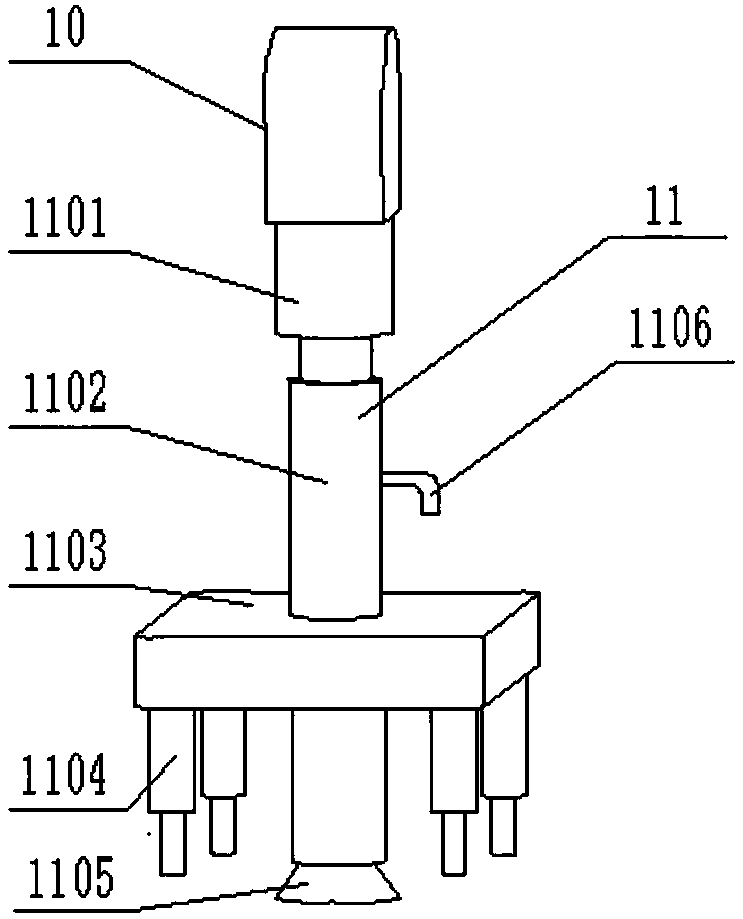
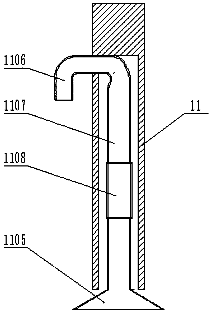
[0012] A photo automatic cutting robot is composed of base 1, film placing box 2, film taking box 3, CCD bracket 4, CCD camera 5, base motor 6, vertical cylinder 7, vertical cylinder connecting block 8, horizontal cylinder 9, horizontal cylinder The connecting block 10, the claw 11, the fixed plate bracket 12, the fixed plate 13, the crank 14, the connecting rod 15, the cutter 16, the crank motor bracket 17, the crank motor 18 and the control box 19 are composed of: a film box 2 and the cassette 3 are installed on both sides of the base 1, the CCD bracket 4 is fixed on the base 1, the CCD camera 5 is installed on the CCD bracket 4, the base motor 6 is fixed on the base 1, the vertical cylinder 7 is installed on the base motor 6, the horizontal cylinder 9 and the vertical cylinder 7 are connected by the vertical cylinder connecting block 8, the claw 11 is installed on the horizontal cylinder 9 through the horizontal cylinder connecting block 10, the fixing plate bracket 12 is fix...
PUM
Abstract
An automatic photo cutting robot a base, a photo placing box, a photo taking box, a CCD (charge coupled device) support, a CCD camera, a base motor, a vertical cylinder, a vertical-cylinder connecting block, a horizontal cylinder, a horizontal-cylinder connecting block, a gripper, a fixing-plate support, a fixing plate, a crank, a connecting rod, a cutter, a crank motor support, a crank motor and a control box. The automatic photo cutting robot is characterized in that the photo placing box, the photo taking box, the CCD support, the base motor, the fixing-plate support and the control box are fixed on the base, the CCD camera is installed on the CCD support, the vertical cylinder is installed on the base motor, the horizontal cylinder and the vertical cylinder are connected through the vertical-cylinder connecting block, the gripper is connected onto the horizontal cylinder through the horizontal-cylinder connecting block, the fixing plate is mounted on the fixing-plate support, the crank, the connecting rod, the cutter and the fixing plate are mutually connected, the crank motor is connected with the crank, and the crank motor is fixed on the base through the crank motor support. By the arrangement, photos can be cut automatically.
Description
Technical field [0001] The invention relates to an automatic photo-cutting robot, in particular to a device which can automatically cut photographs composed of a base, a CCD camera, a gripper, a control box, etc., and belongs to the field of office appliances. Background technique [0002] After the photo is printed, there will be a white blank area around it. This area needs to be cropped. The current cropping method is to use a paper cutter or scissors to crop each photo. The cropping staff needs to cut each photo one by one by hand , This cutting method wastes manpower and is inefficient. Summary of the invention [0003] In view of the above-mentioned shortcomings, the present invention provides an automatic photo-cutting robot. [0004] The present invention is realized through the following technical solutions: a photo automatic cutting robot, which is composed of a base, a film box, a film take box, a CCD bracket, a CCD camera, a base motor, a vertical cylinder, a vertical c...
Claims
Application Information
Patent Timeline
Application Date:The date an application was filed.
Publication Date:The date a patent or application was officially published.
First Publication Date:The earliest publication date of a patent with the same application number.
Issue Date:Publication date of the patent grant document.
PCT Entry Date:The Entry date of PCT National Phase.
Estimated Expiry Date:The statutory expiry date of a patent right according to the Patent Law, and it is the longest term of protection that the patent right can achieve without the termination of the patent right due to other reasons(Term extension factor has been taken into account ).
Invalid Date:Actual expiry date is based on effective date or publication date of legal transaction data of invalid patent.