Transformer transport device with protective function

A technology of transportation device and protective function, which is applied in the field of transformer transportation device with protective function, which can solve the problems of damaged parts, complex internal structure, and high labor intensity, and achieve the effect of convenient use, easy installation, and reduced labor intensity

Active Publication Date: 2017-12-29
怀宁板桥电子有限公司
View PDF4 Cites 4 Cited by
  • Summary
  • Abstract
  • Description
  • Claims
  • Application Information

AI Technical Summary

Problems solved by technology

[0003] Because the weight of the transformer is relatively large, the internal structure is relatively complicated, there are many parts, and it is relatively expensive, so it is necessary to protect the transformer during transportation, so as not to cause misalignment or damage to the internal parts during transportation, resulting in overall damage. Traditional transportation , just put it in a cardboard box or a wooden box, and then transport it with a large transport vehicle. The transformer needs to be placed in different places, and the road the transport vehicle travels will be different. If you encounter a bumpy driveway, the shaking back and forth may It will cause damage to the parts in the transformer. Although the appearance is not damaged, the internal damage will directly affect the service life or whether it can be used again. If it is placed in a sealed box that is easy to protect, it is inconvenient to take the transformer. When the transformer is installed in the airtight box, it needs to be put in manually, and the transformer needs to be lifted. The labor intensity is relatively large. Therefore, in order to solve these problems, it is very important to design a transformer transportation device that is easy to protect. necessary

Method used


Image

  • Transformer transport device with protective function
  • Transformer transport device with protective function
  • Transformer transport device with protective function

Examples


Embodiment Construction

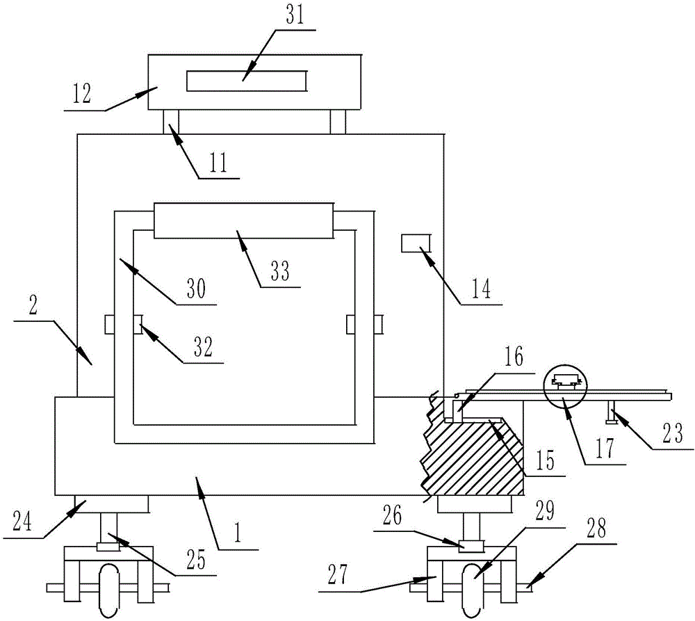
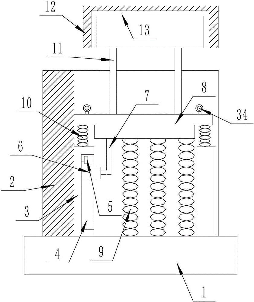
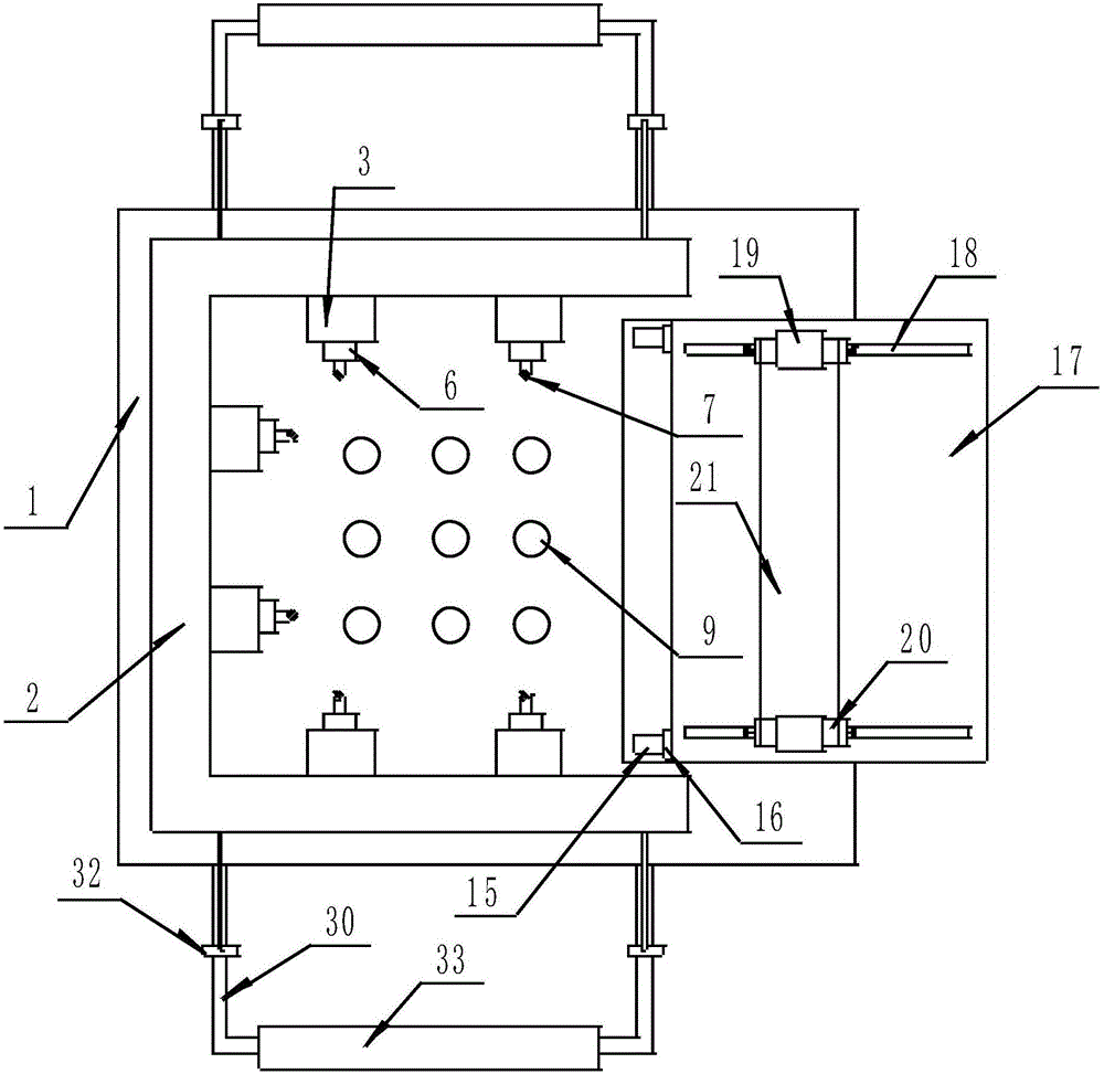
[0021] The present invention is specifically described below in conjunction with accompanying drawing, as Figure 1-4 As shown, a transformer transport device with a protective function includes a strip bearing plate 1, the upper surface of the strip bearing plate 1 is provided with a protective transport mechanism, and the side surface of the strip bearing plate 1 is provided with a protection transport mechanism. The inclined feeding mechanism overlapping the mechanism, the lower surface of the strip bearing plate 1 is provided with a moving mechanism, and the protective transport mechanism is fixedly connected to the N-shaped frame 2 on the upper surface of the strip bearing plate 1, fixedly connected to the N A plurality of vertical fixed plates 3 on the inside surface of the shape frame 2, open the vertical slideway on each vertical fixed plate 3 side surfaces, be arranged on the inner upper end of each vertical slideway 4 and be connected with the N-shaped frame 2 The lo...


PUM


Abstract

The invention discloses a transformer transport device with a protective function. The transformer transport device comprises a strip-shaped bearing plate, wherein a protective transport mechanism is arranged on the upper surface of the strip-shaped bearing plate; an inclined loading mechanism lapped with the protective transport mechanism is arranged on the side surface of the strip-shaped bearing plate; and a movement mechanism is arranged on the lower surface of the strip-shaped bearing plate. The device disclosed by the invention has the following beneficial effects: the device is convenient to use; placement for a transformer on the device is facilitated, the transformer can be effectively protected from being collided in the processes of transport and movement, and during installation, lifting for a part of the device with the transformer is facilitated, and installation is facilitated, so that the labor intensity is lowered, and the needs of people are better met.

Description

technical field [0001] The invention relates to the field of transformer transportation, in particular to a transformer transportation device with a protective function. Background technique [0002] Transformers are used to convert the voltage to and from electricity and are usually placed on utility poles out of reach of people. [0003] Because the weight of the transformer is relatively large, the internal structure is relatively complicated, there are many parts, and it is relatively expensive, so it is necessary to protect the transformer during transportation, so as not to cause misalignment or damage to the internal parts during transportation, resulting in overall damage. Traditional transportation , just put it in a cardboard box or a wooden box, and then transport it with a large transport vehicle. The transformer needs to be placed in different places, and the road the transport vehicle travels will be different. If you encounter a bumpy driveway, the shaking bac...

Claims


Application Information

Patent Timeline
IPC IPC(8): B65D25/02B65D81/07B65D81/127B65D85/68
CPCB65D25/02B65D81/07B65D81/127B65D85/68
Inventor 李珅
Owner 怀宁板桥电子有限公司
Why Eureka
Try Eureka