Slotted cable bridge connecting structure

A cable tray and connection structure technology, applied in the direction of electrical components, etc., can solve problems such as time-consuming and laborious, delaying work progress, troublesome operation, etc., to avoid damage, improve rigidity and stability, and speed up internal drying.

Inactive Publication Date: 2017-12-29
江苏大浪电气集团有限公司
View PDF8 Cites 6 Cited by
  • Summary
  • Abstract
  • Description
  • Claims
  • Application Information

AI Technical Summary

Problems solved by technology

[0005] The purpose of the present invention is to provide a slotted cable bridge connection structure, which solves the problem of troublesome operation, time-consuming and laborious operation, and serious delay in the work progress during the installation process of the current cable bridge.

Method used


Image

  • Slotted cable bridge connecting structure
  • Slotted cable bridge connecting structure
  • Slotted cable bridge connecting structure

Examples


Embodiment Construction

[0026] The following will clearly and completely describe the technical solutions in the embodiments of the present invention with reference to the accompanying drawings in the embodiments of the present invention. Obviously, the described embodiments are only some, not all, embodiments of the present invention. Based on the embodiments of the present invention, all other embodiments obtained by persons of ordinary skill in the art without making creative efforts belong to the protection scope of the present invention.

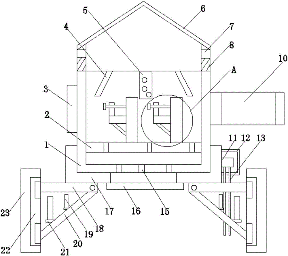
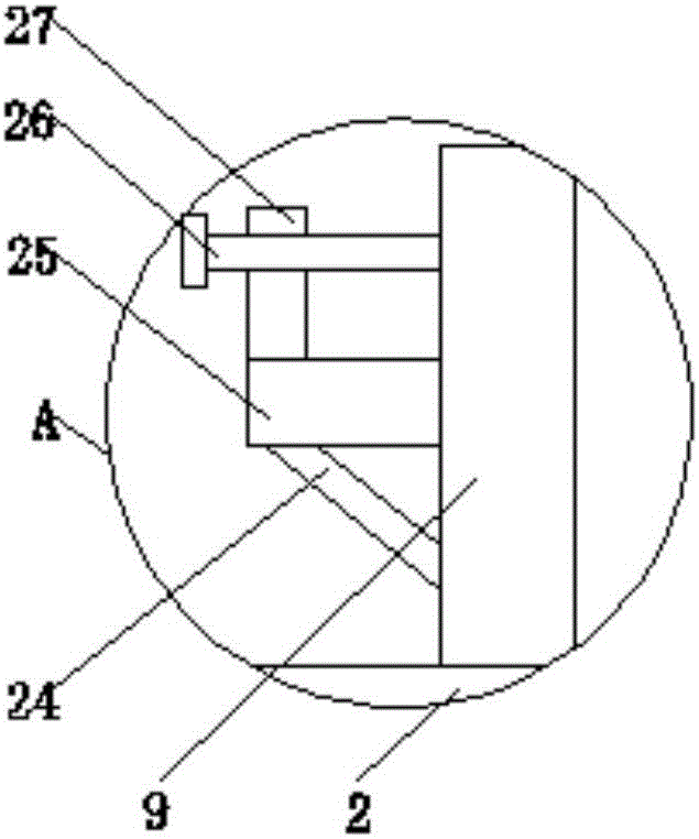
[0027] like Figure 1-4As shown, the embodiment of the present invention provides a trough-type cable bridge connection structure, including a first tank body 1, and an angle steel 17 is fixedly connected to the bottom of the first tank body 1, and the angle steel 17 is fixed on the bottom of the first tank body 1, To enhance the strength and load capacity of the first tank body 1, one side of the angle steel 17 is fixedly connected with a connecting block 11,...


PUM


Abstract

The invention discloses a slotted cable bridge connecting structure comprising a first slot body. Angle steel is fixedly connected on the bottom part of the first slot body. Reinforcing ribs are fixedly connected on the internal side of the angle steel. Supporting rods are welded on the bottom part of the angle steel. A support rod is hinged on one end of each supporting rod. A first slide block is hinged on the left end of each support rod. The first slot body, a second slot body, a baffle plate, a guide plate and a pulley are arranged. The baffle plate limits the movement of the second slot body. The first slot body and the second slot body are enabled to be connected by sliding of the pulley on the guide plate and guidance of the guide plate so that fixing and welding are facilitated. A rotating rod, a groove and a buffer spring are arranged, the rotating rod rotates around the connecting shaft along with sliding of the pulley, and an adjusting spring adjusts the movement of the rotating rod so that the pulley is enabled to be fit with the guide plate for connection. The angle steel, the reinforcing ribs, the supporting rods and the installing plate are arranged, and the angle steel and the reinforcing ribs are matched with each other so that the overall rigidity and stability can be enhanced.

Description

technical field [0001] The invention relates to the technical field of trough type cable bridges, in particular to a trough type cable bridge connection structure. Background technique [0002] Trough-type cable tray is a trough-shaped component bent from a whole steel plate. The conceptual difference between it and the pan frame is that the height and width ratio are different. The pan frame is shallow and wide. The trough-type cable tray has a certain depth and closure. , is the full name of a rigid structural system with close-fitting supporting cables composed of straight sections, bends, components, brackets (arm brackets) and hangers of pallets or ladder frames. [0003] The trough cable tray can be used for fully enclosed cable laying. It is most suitable for laying computer cables, communication cables, thermocouple cables and other control cables for high-sensitivity systems. It can shield interference to control cables and cables in heavy corrosion environments. p...

Claims


Application Information

Patent Timeline
Patent Type & Authority Applications(China)
IPC IPC(8): H02G3/04
CPCH02G3/0456H02G3/0406H02G3/0412
Inventor 施大春刘坤杨瑞峰
Owner 江苏大浪电气集团有限公司
Why Eureka
Try Eureka