
DC current limiter and its driving method

A technology of current limiter and DC current, which is applied in the field of power transmission and distribution, and can solve the problems of few multi-terminal transmissions, failures, and DC current upscaling and switching.

Active Publication Date: 2019-12-27
ELECTRIC POWER RESEARCH INSTITUTE, CHINA SOUTHERN POWER GRID CO LTD
View PDF6 Cites 0 Cited by
  • Summary
  • Abstract
  • Description
  • Claims
  • Application Information

AI Technical Summary

Problems solved by technology

[0003] Most of the current DC transmission systems are point-to-point transmission, and there are very few multi-terminal transmissions. The main reason for this problem is that there is no effective measure to limit the fault DC current when the DC transmission system fails, and the DC current rises rapidly during the fault period. commutation failure

Method used


Image

  • DC current limiter and its driving method
  • DC current limiter and its driving method
  • DC current limiter and its driving method

Examples


Embodiment Construction

[0024] In order to make the above objects, features and advantages of the present invention more obvious and understandable, the technical solutions in the embodiments of the present invention will be clearly and completely described below in conjunction with the drawings in the embodiments of the present invention. Apparently, the described embodiments are only some of the embodiments of the present invention, but not all of them. Based on the embodiments of the present invention, all other embodiments obtained by persons of ordinary skill in the art without creative efforts fall within the protection scope of the present invention.

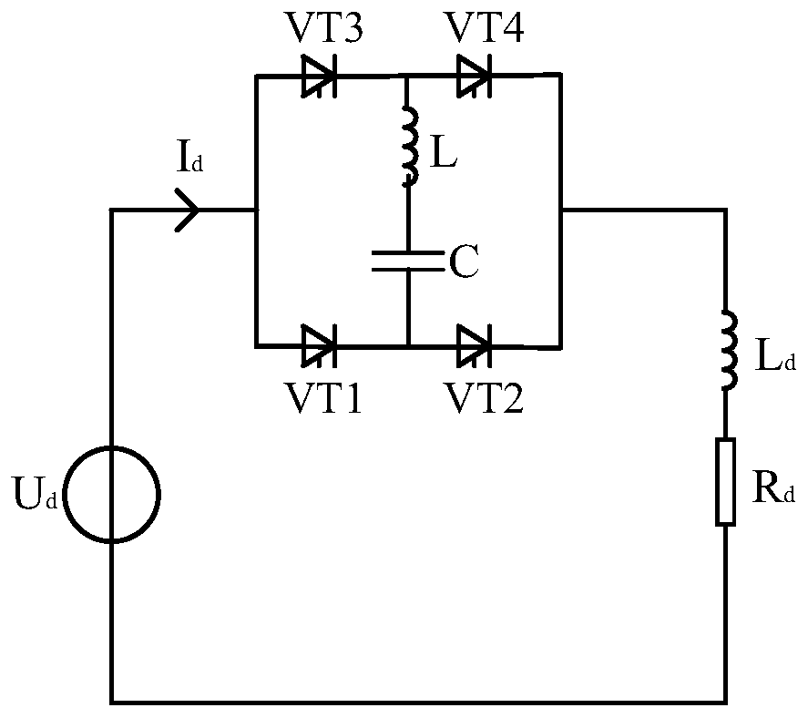
[0025] The embodiment of the present invention provides a DC current limiter topology, such as figure 1 As shown, the structure of the DC current limiter includes a bridge structure, specifically including: four bridge arms, a reactor and a capacitor.

[0026] Among them, the four bridge arms are the first upper bridge arm VT1, the first lower ...


PUM


Abstract

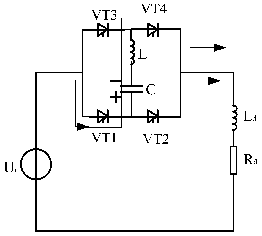
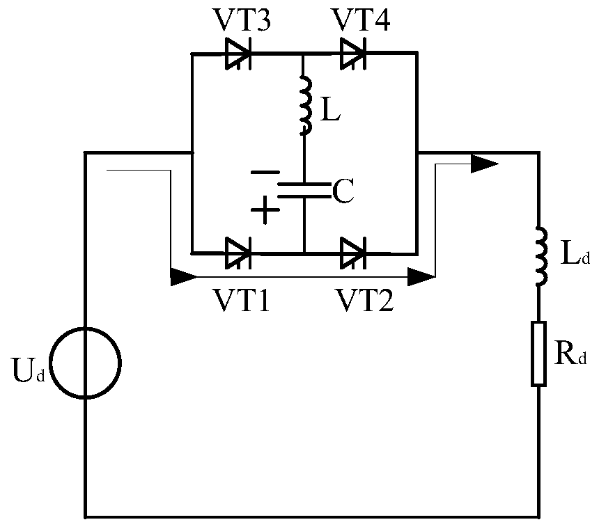
The invention provides a DC current limiter topology, a drive method therefor and a DC current limiter, and relates to the technical field of power transmission and distribution. A DC fault current can be limited, and the probability of phase change failure of a system is reduced. The DC current limiter topology comprises four bridge arms: a first upper bridge arm, a first lower bridge arm, a second upper bridge arm, and a second lower bridge arm. The four bridge arms are respectively formed by the series connection of a plurality of thyristors. The first upper and lower bridge arms are connected in series, and the second upper and lower bridge arms are connected in series. Moreover, a branch circuit formed by the series connection of the first upper and lower bridge arms is in parallel connection with a branch circuit formed by the series connection of the second upper and lower bridge arms. The DC current limiter topology also comprises a reactor and a capacitor, which are connected in series. One end of a branch circuit formed by the series connection of the reactor and the capacitor is connected between the first upper and lower bridge arms, and the other end of the branch circuit is connected between the second upper and lower bridge arms. According to the invention, the technical scheme is applied in a DC system, and a direct current is limited when the system has a fault.

Description

technical field [0001] The invention relates to the technical field of power transmission and distribution, in particular to a DC current limiter and a driving method thereof. Background technique [0002] With the continuous improvement of my country's transmission capacity and the development of power electronics technology, HVDC transmission has been widely used in long-distance and large-capacity transmission due to its unique technical and economic advantages. The traditional point-to-point DC transmission system can be expanded into a DC grid, of which the flexible DC transmission grid is the main development direction, which has many characteristics of stable and reliable grids, and also provides convenience for large-scale access of distributed energy. [0003] Most of the current DC transmission systems are point-to-point transmission, and there are very few multi-terminal transmissions. The main reason for this problem is that there is no effective measure to limit...

Claims


Application Information

Patent Timeline
Patent Type & Authority Patents(China)
IPC IPC(8): H02M1/32H02H9/02H02J3/36
CPCH02H9/021H02J2003/365H02M1/32Y02E60/60
Inventor 李春华李明李岩黄莹饶宏曹润彬郭铸黄伟煌刘涛陈怡静李婧靓
Owner ELECTRIC POWER RESEARCH INSTITUTE, CHINA SOUTHERN POWER GRID CO LTD
Learn More