Water cooling granary

A water-cooled, granary technology, applied in fruit hanging devices, climate change adaptation, botanical equipment and methods, etc., can solve the problems of high operating costs, unsatisfactory cooling effect, large power consumption, etc., to save energy and avoid idle Large space and uniform cooling effect

Active Publication Date: 2018-01-05
黄世强
7 Cites 0 Cited by

AI-Extracted Technical Summary

Problems solved by technology

However, in these existing technologies, the cold air generated by the air conditioner cannot enter the grain pil...

Method used

In above-mentioned technical scheme, granary body 1 is cuboid shape, and interior is hollow, and dividing plate 4 divides granary body 1 into two chambers, i.e. cooling area 12 and grain storage area 11, and grain storage area 11 is used for stacking Grain pile. The dividing plate 4 is provided with the first opening and the second opening spaced up and down, the upper moving block 2 can stretch into the grain storage area 11 from the first opening, the lower moving block 3 can stretch into the grain storage area 11 from the second opening, and the upper The array of moving blocks 2 just covers the first opening, and the array of lower moving blocks 3 just covers the second opening. It can be seen that through the upper moving block 2 and the lower moving block 3, the space of the grain storage area 11 can be changed, and a space of a suitable size is also convenient for cooling, which is more energy-saving. After the space is determined, the array of the upper moving block 2 is used as the grain storage area 11 The cover, the lower moving block 3 arrays are used as the bottom surface of the grain storage area 11. Both the upper moving block 2 and the lower moving block 3 are provided with a water flow channel, that is, water can flow therein, and the coil pipe 5 is used to supply water with a lower temperature for the water flow channel, thereby reducing the temperature of the grain pile in the grain storage area 11, Since the upper moving block 2 and the lower moving block 3 are respectively located at the top and the bottom of the grain pile and are closely arranged, the temperature of the grain pile can be cooled rapidly and evenly. There are two ways to reduce the temperature of the water in the coil pipe 5, one is to use the induc...

Abstract

The invention discloses a water cooling granary. The water cooling granary is characterized by comprising a granary body, multiple upper moving blocks, multiple lower moving blocks, a coil pipe and aninduced draft fan, wherein a partition plate is vertically arranged in the granary body and partitions the granary body into a heat dissipating region and a grain storing region; the cross section area sum of an upper moving block array of the upper moving blocks is equal to the area of a first opening, the cross section area sum of a lower moving block array of the lower moving blocks is equal to the area of a lower opening of the granary body, and U-shaped water flow channels are formed in the upper moving blocks and the lower moving blocks; a water inlet and a water outlet of the coil pipeare communicated with water outlets and water inlets of the water flow channels respectively, and the surface of the coil pipe is attached to the cold end of a semiconductor chilling plate; the induced draft fan is arranged on an air inlet, and the air outlet direction of the induced draft fan is vertical to the coil pipe plane. The water cooling granary is capable of using natural low temperature for cooling grain to save energy on one hand and using water heat transfer for cooling on the other hand, and cooling is high in speed and uniform.

Application Domain

Technology Topic

Image

  • Water cooling granary
  • Water cooling granary
  • Water cooling granary

Examples

  • Experimental program(1)

Example Embodiment

[0024] The present invention will be further described in detail below with reference to the accompanying drawings, so that those skilled in the art can implement it with reference to the text of the description.
[0025] It should be understood that terms such as "having", "including" and "including" used herein do not equate the presence or addition of one or more other elements or combinations thereof.
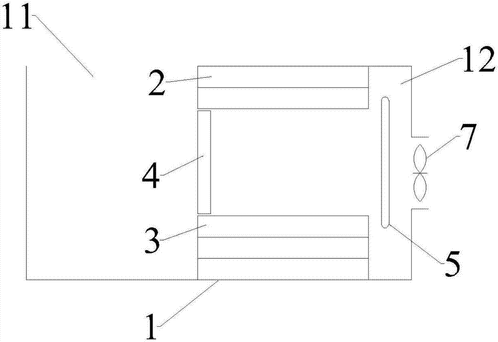
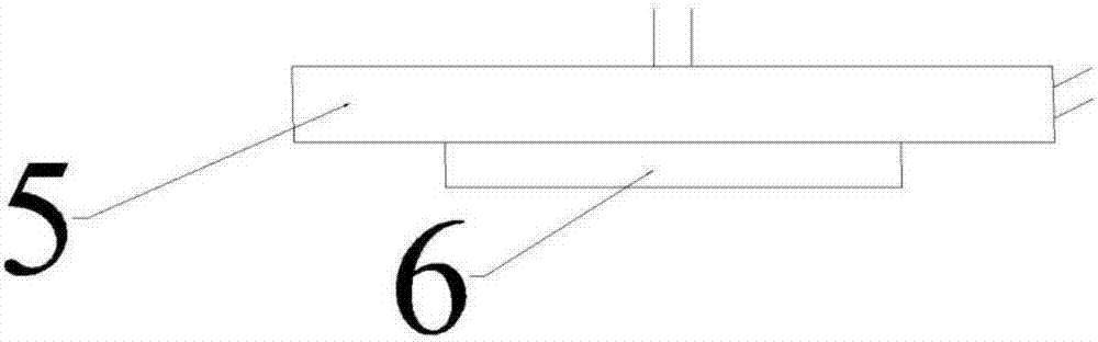
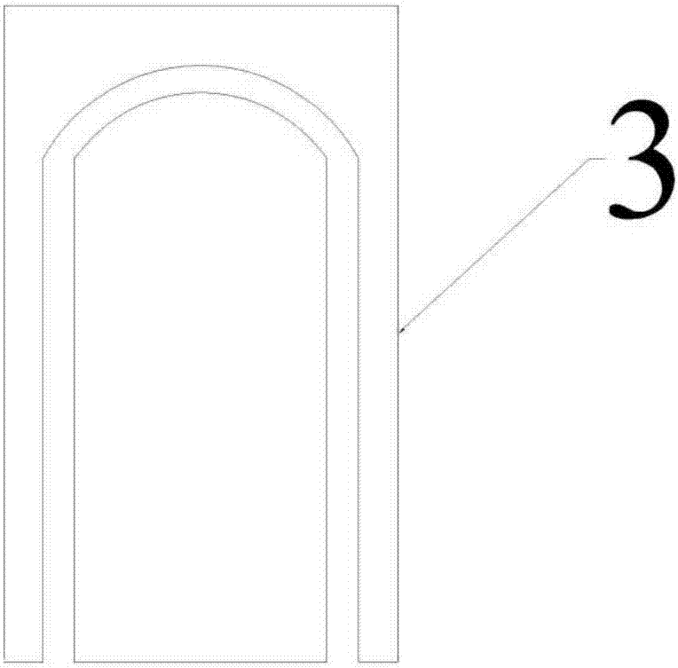
[0026] Such as figure 1 , 2 As shown in 3, the present invention provides a water-cooled granary, including:
[0027] The granary body 1 is a vertically arranged rectangular parallelepiped structure. The granary body 1 is vertically provided with a partition 4 inside which is parallel to a pair of parallel sides of the granary body 1, and the partition 4 The granary body 1 is divided into a heat dissipation area 12 and a grain storage area 11. The grain storage area 11 is used for stacking grain, the upper part of the partition 4 is provided with a first opening, and the lower part of the partition 4 is provided with a first opening. Two openings, the first opening and the second opening are both rectangular with a length equal to the width of the partition 4;
[0028] A plurality of upper moving blocks 2 and a plurality of lower moving blocks 3, the plurality of upper moving blocks 2 and the plurality of lower moving blocks 3 are each a rectangular parallelepiped structure, the plurality of upper moving blocks 2 and the plurality of The lower moving blocks 3 are horizontally arranged in the heat dissipation area 12, and their axes are all perpendicular to the surface of the partition board 4. The plurality of upper moving blocks 2 are arranged in an array of upper moving blocks 2 by tightly fitting the side surfaces. A plurality of lower moving blocks 3 are arranged in an array of lower moving blocks 3 by closely adhering side surfaces. The sum of the cross-sectional area of ​​the upper moving block 2 array is equal to the area of ​​the first opening, and the position is the same as that of the first opening. Corresponding to the opening, the sum of the cross-sectional area of ​​the lower moving block 3 array is equal to the area of ​​the lower opening of the granary body 1, and the position corresponds to the second opening, the upper moving block 2 and the lower moving block 2 The blocks 3 are all driven by air cylinders, and are arranged in such a way that the upper moving block 2 and the lower moving block 3 can move from the first position to the second position along the horizontal direction. When the upper moving block 2 and the When the lower moving block 3 is in the first position, the end surfaces of the upper moving block 2 and the lower moving block 3 close to the grain storage area 11 are flush with the surface of the partition 4, and when the upper moving block 2 When the upper moving block 2 and the lower moving block 3 are in the second position, the end faces of the upper moving block 2 and the lower moving block 3 close to the grain storage area 11 are parallel to the side surface of the granary body 1 and the partition 4 To the top, the upper moving block 2 and the lower moving block 3 are both provided with a U-shaped water flow channel, and the water inlet and the water outlet of the water flow channel are both set at the upper moving block 2 and the lower moving block 3 close to The end surface of the heat dissipation area 12;
[0029] The coil 5 has a mosquito-repellent-like structure wound by folding a metal tube. The contour of the coil 5 conforms to the Archimedes spiral. The water inlet and the water outlet of the coil 5 are both located on the coil. On the edge of the tube 5, the water inlet and the water outlet of the coil 5 are respectively connected with the water outlet and the water inlet of the water flow channel, and the surface of the coil 5 is also attached to the cold end of a semiconductor refrigeration fin 6, so The plane of the coil 5 is along the vertical direction;
[0030] An induced draft fan 7 is provided with an air inlet on the side of the granary body 1 corresponding to the heat dissipation area 12, and an induced draft fan 7 is arranged on the inlet. The outlet direction of the induced draft fan 7 is consistent with the coil 5 The plane is vertical.
[0031] In the above technical solution, the granary body 1 has a rectangular parallelepiped shape with a hollow interior. The partition 4 divides the granary body 1 into two chambers, namely a heat dissipation area 12 and a grain storage area 11, and the grain storage area 11 is used for stacking grain piles. The partition 4 is provided with a first opening and a second opening spaced up and down. The upper moving block 2 can extend into the grain storage area 11 from the first opening, and the lower moving block 3 can extend into the grain storage area 11 from the second opening. The array of moving blocks 2 just covers the first opening, and the array of lower moving blocks 3 just covers the second opening. It can be seen that through the upper moving block 2 and the lower moving block 3, the space of the grain storage area 11 can be changed. A suitable size of space is also convenient for cooling and energy saving. After the space is determined, the upper moving block 2 array is used as the grain storage area 11. The lower moving block 3 array is used as the bottom surface of the grain storage area 11. Both the upper moving block 2 and the lower moving block 3 are provided with water flow channels, that is, water can flow in them, and the coil 5 is used to supply lower temperature water to the water flow channels, thereby reducing the temperature of the grain pile in the grain storage area 11. Since the upper moving block 2 and the lower moving block 3 are respectively located at the top and bottom of the grain pile and are closely arranged, the temperature of the grain pile can be quickly and evenly cooled. There are two ways to reduce the temperature of the water in the coil 5, one is to use the induced draft fan 7 to suck in cold air from nature, and the other is to use the semiconductor refrigeration fins 6 to cool the temperature. The coil 5 is designed as a mosquito-repellent-like structure wound by folding a metal tube, which is convenient and quick to cool down, and takes up a small space. In summary, this technical solution can change the space of the grain storage area 11, and can utilize natural cold sources, which is more energy-efficient.
[0032] In another technical solution, the water-cooled low-temperature granary further includes:
[0033] A first temperature sensor and a second temperature sensor, the first temperature sensor is arranged inside the grain for detecting the internal temperature of the grain pile, and the second temperature sensor is arranged outside the granary body 1 for detecting the external ambient temperature;
[0034] The controller is electrically connected to the cylinder, the induced draft fan 7, the semiconductor refrigeration fin 6, the first temperature sensor and the second temperature sensor. When the internal temperature of the grain pile is higher than the preset value, And the external environment temperature is lower than the first threshold value, the induced draft fan 7 is turned on. When the internal temperature of the grain pile is higher than the preset value and the external environment temperature is higher than the first threshold value, the semiconductor refrigeration fin 6 is energized.
[0035] In the above technical solution, two different conditions for cooling the coil 5 are provided, that is, when the internal temperature of the grain reaches a preset value (ie, the safety critical value), it is selected according to the external environment temperature to suck in cold air or semiconductor refrigeration The sheet 6 is energized to cool down. When the external environment temperature is lower than the first threshold value, cold air is sucked in, and when the temperature is higher than the first threshold value, the semiconductor refrigeration sheet 6 is used to cool down. Here, the first threshold may be 10-15°C, and the preset value is selected and determined according to different grains.
[0036] In another technical solution, in the water-cooled low-temperature granary, the outer wall of the granary body 1 is provided with a thermal insulation layer. Here, the insulation layer is used to reduce the leakage of cold in the grain storage area 11.
[0037] In another technical solution, in the water-cooled low-temperature granary, the cross-sections of the upper moving block 2 and the lower moving block 3 are square, and the length of the first opening is the same as that of the upper moving block 2. 8 times the side length of the cross section, the width of the first opening is twice the side length of the cross section of the upper moving block 2, and the length of the second opening is 16 times the side length of the cross section of the lower moving block 3 The width of the second opening is 4 times the side length of the cross section of the upper moving block 2. Here, an optional realization form of the upper moving block 2 and the lower moving block 3 is provided, that is, a 2*8 array and a 4*16 array are formed. In this realization form, the grain pile cools more evenly and quickly. When the upper part moves The side lengths of block 2 and lower moving block 3 are further increased, and the cooling effect of the grain pile decreases.
[0038] In another technical solution, in the water-cooled granary, the upper moving block 2 and the lower moving block 3 are both made of thermally conductive materials. Here, the heat-conducting material facilitates water to cool the grain pile.
[0039] In another technical solution, in the water-cooled granary, a damper is further provided in the air inlet, and the damper closes the air inlet when the semiconductor refrigeration sheet 6 is energized. Here, close the damper to reduce the leakage of cold energy and reduce energy loss.
[0040] The number of equipment and processing scale described here are used to simplify the description of the present invention. The applications, modifications and changes to the granary of the present invention are obvious to those skilled in the art.
[0041] Although the embodiments of the present invention have been disclosed above, they are not limited to the applications listed in the specification and embodiments. It can be applied to various fields suitable for the present invention. For those skilled in the art, it can be easily Therefore, without departing from the general concept defined by the claims and equivalent scope, the present invention is not limited to the specific details and the illustrations shown and described here.

PUM

no PUM

Description & Claims & Application Information

We can also present the details of the Description, Claims and Application information to help users get a comprehensive understanding of the technical details of the patent, such as background art, summary of invention, brief description of drawings, description of embodiments, and other original content. On the other hand, users can also determine the specific scope of protection of the technology through the list of claims; as well as understand the changes in the life cycle of the technology with the presentation of the patent timeline. Login to view more.

Similar technology patents

Vibration sounding device and electronic equipment

ActiveCN110049415ASimple structureEnergy savingTransducers for sound channels pluralityLoudspeaker screensAudio signalAudio frequency
Owner:HUAWEI TECH CO LTD

Dimming method for infrared camera

Owner:SKY LIGHT ELECTRONICS SHENZHEN

Classification and recommendation of technical efficacy words

  • Uniform cooling
  • Energy saving

Steel plate manufacturing facility and manufacturing method

InactiveUS20120017660A1Little surface temperature deviationUniform coolingTensioning/braking arrangementsExtrusion cleaning devicesSteel platesEngineering
Owner:JFE STEEL CORP
Why Eureka
Try Eureka