
X-ray imaging device and its detector deflection mechanism

The technology of an imaging device and a deflection mechanism, which is applied in the fields of radiological diagnostic instruments, medical science, and diagnosis, can solve the problems of high price and increased cost of radiation sources, and achieve low cost, expanded imaging field of view, and wide imaging field of view Effect

Active Publication Date: 2020-05-15
HEFEI MEIYA OPTOELECTRONICS TECH
View PDF13 Cites 0 Cited by
  • Summary
  • Abstract
  • Description
  • Claims
  • Application Information

AI Technical Summary

Problems solved by technology

Among them, the detector is an important part of the X-ray imaging device. The larger the image imaging area, the larger the shooting field of view, and the more expensive the price. The radiation can cover the entire imaging area of ​​the detector. The larger the imaging area of ​​the detector image, the larger the source cone angle of the required source device, and the cost of the source device will increase accordingly.

Method used


Image

  • X-ray imaging device and its detector deflection mechanism
  • X-ray imaging device and its detector deflection mechanism
  • X-ray imaging device and its detector deflection mechanism

Examples


Embodiment Construction

[0045] Embodiments of the present invention are described in detail below, examples of which are shown in the drawings, wherein the same or similar reference numerals designate the same or similar elements or elements having the same or similar functions throughout. The embodiments described below by referring to the figures are exemplary and are intended to explain the present invention and should not be construed as limiting the present invention.

[0046] The X-ray imaging devices in the related art are divided into two categories: one is the X-ray imaging device facing directly, that is, the vertical plane where the rotation axis of the rotary gantry is located bisects the detector, and the rotary gantry rotates 180° for 3D reconstruction during work. The other type is an offset X-ray imaging device, such as the vertical plane where the axis of rotation of the rotary gantry is flush with the edge of the detector, and the rotary gantry rotates 360° for 3D reconstruction duri...


PUM


Abstract

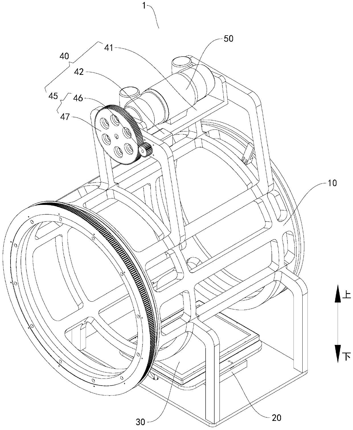
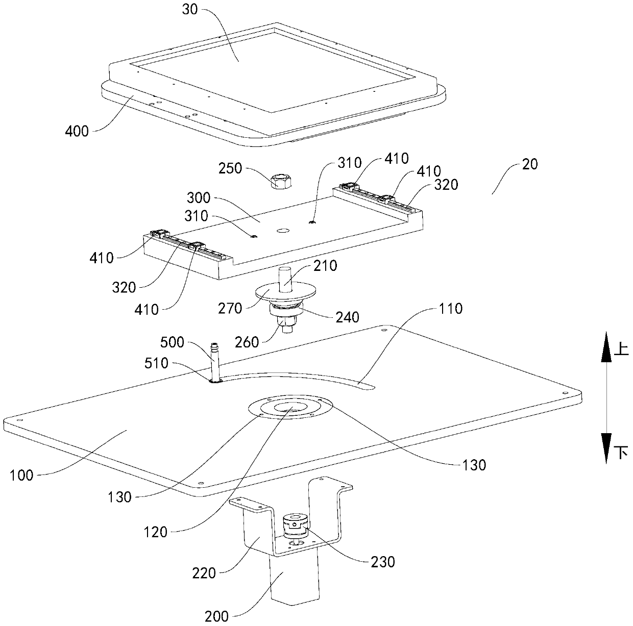
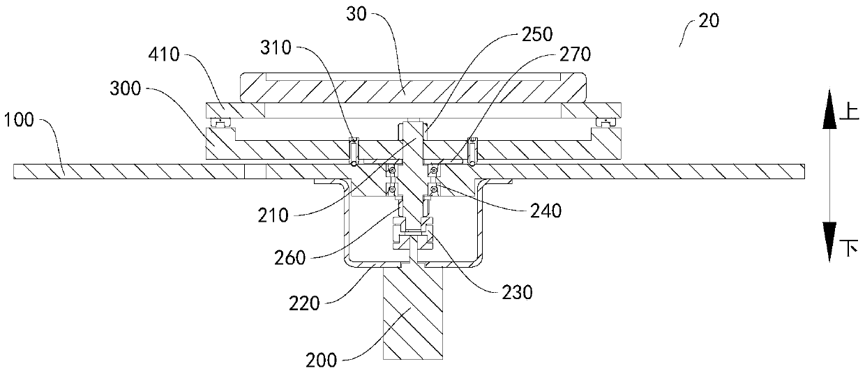
The invention discloses an X-ray imaging device and a detector deflection mechanism thereof. The detector deflection mechanism comprises a substrate, a rotation motor, a revolving bed, a detector mounting board used to mount a detector, and an offset guide rod. The substrate is provided with an offset guide groove. The rotation motor is arranged on the substrate. The revolving bed and the rotationmotor are connected in a transmission manner, and rotation of the revolving bed is driven by the rotation motor. The detector mounting board is moveably arranged on the revolving bed. The offset guide rod is connected with the detector mounting board, and is moveably cooperated in the offset guide groove along the offset guide groove. When the revolving bed rotates driven by the rotation motor, the detector mounting board is driven to rotate, and the detector mounting board moves relative to the revolving bed under the action of the offset guide rod which moves along the offset guide groove.The detector deflection mechanism of the X-ray imaging device can expand imaging view, and cost is relatively low.

Description

technical field [0001] The present invention relates to the technical field of medical equipment, in particular to a detector deflection mechanism for an X-ray imaging device and an X-ray imaging device having the detector deflection mechanism for an X-ray imaging device. Background technique [0002] In the related art, X-ray imaging devices such as CT (computerized tomography) machine and CBCT (cone beam computerized tomography) machine are widely used in medical detection, mainly including a rotary frame and a relative Set up emitters and detectors. Among them, the detector is an important part of the X-ray imaging device. The larger the image imaging area, the larger the shooting field of view, and the more expensive the price. The rays can cover the entire imaging area of ​​the detector. The larger the imaging area of ​​the detector image, the larger the source cone angle of the required source device, and the cost of the source device will increase accordingly. Cont...

Claims


Application Information

Patent Timeline
Patent Type & Authority Patents(China)
IPC IPC(8): A61B6/00A61B6/03
Inventor 徐明峰刘全忠张建军
Owner HEFEI MEIYA OPTOELECTRONICS TECH
Learn More