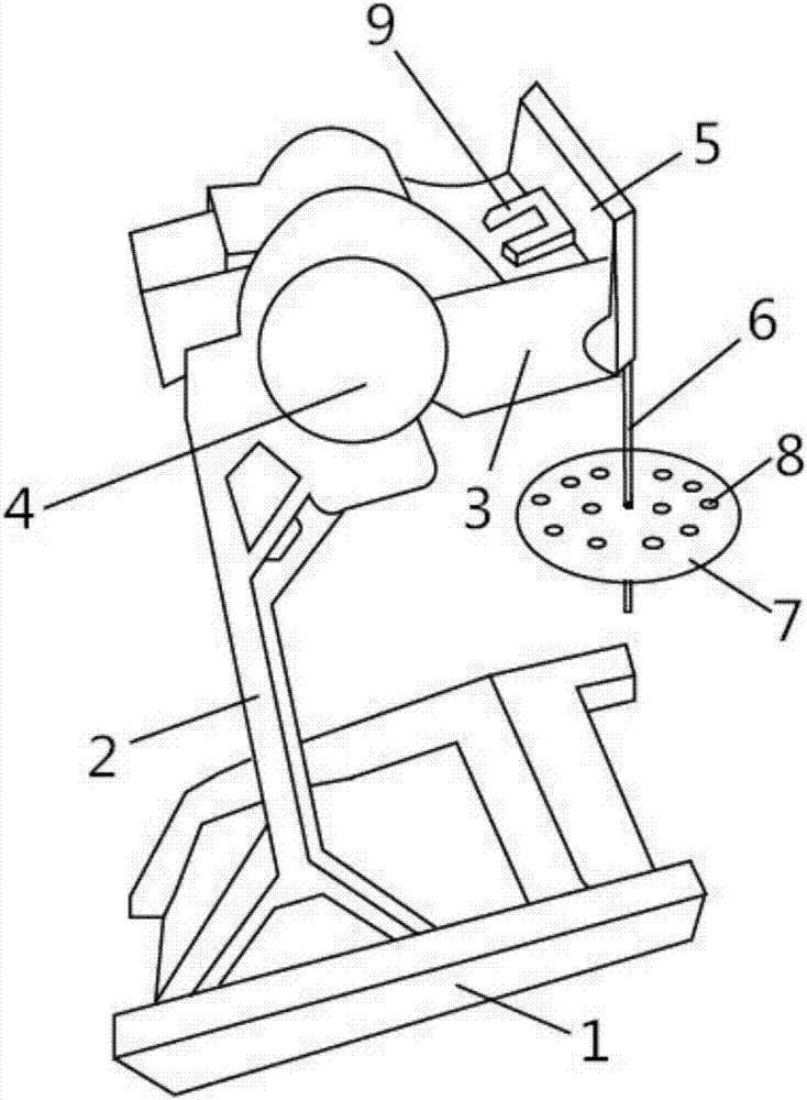
A material stirring device
A stirring device and material technology, applied to mixers with rotating stirring devices, mixer accessories, transportation and packaging, etc., can solve the problems of low efficiency, troublesome efficiency, difficult control, etc., achieve good mixing effect, convenient maintenance, The effect of simple structure
- Summary
- Abstract
- Description
- Claims
- Application Information
AI Technical Summary
Problems solved by technology
Method used
Image
Examples
Embodiment 1
[0016] A material stirring device, comprising a base 1, a support beam 2, a beam 3, an adjustment device 4, a power unit, and a stirring device 5, the base 1 is provided with a support beam 2, the support beam 2 is provided with a beam 3, and the beam 3 is provided with a Adjustment device 4 is arranged, crossbeam 3 and stirring device 5 joints are provided with reinforcing device 9, adjustment device 4 is connected with stirring device 5 through described power unit, stirring device 5 comprises stirring rod 6, stirring disc 7, and stirring rod 6 can be The dismantling is installed in the stirring plate 7, and the stirring plate 7 is provided with mounting holes 8.
Embodiment 2
[0018] A material stirring device, comprising a base 1, a support beam 2, a beam 3, an adjustment device 4, a power unit, and a stirring device 5, the base 1 is provided with a support beam 2, the support beam 2 is provided with a beam 3, and the beam 3 is provided with a There is an adjustment device 4, and a reinforcing device 9 is provided at the connection between the beam 3 and the stirring device 5. The adjustment device 4 includes a true gear and a cycloidal wheel, and the cycloidal wheel is in phase with a group of circularly arranged pin teeth on the true gear. Mesh, the adjustment device 4 is connected with the stirring device 5 through the power device, the stirring device 5 includes a stirring rod 6, a stirring plate 7, the stirring rod 6 is detachably installed in the stirring plate 7, and the stirring plate 7 is provided with a mounting hole 8.
Embodiment 3
[0020] A material stirring device, comprising a base 1, a support beam 2, a beam 3, an adjustment device 4, a power unit, and a stirring device 5, the base 1 is provided with a support beam 2, the support beam 2 is provided with a beam 3, and the beam 3 is provided with a There is an adjustment device 4, and a reinforcing device 9 is provided at the connection between the beam 3 and the stirring device 5. The adjustment device 4 includes a true gear and a cycloidal wheel, and the cycloidal wheel is in phase with a group of circularly arranged pin teeth on the true gear. Engagement, the adjustment device 4 is connected with the stirring device 5 through the power device, the output shaft of the power device is provided with a double eccentric sleeve, the stirring device 5 includes a stirring rod 6, a stirring plate 7, and the stirring rod 6 is detachably installed In the stirring plate 7, an installation hole 8 is set up on the stirring plate 7.
PUM
 Abstract
Description
Claims
Application Information
 - R&D
- Intellectual Property
- Life Sciences
- Materials
- Tech Scout
- Unparalleled Data Quality
- Higher Quality Content
- 60% Fewer Hallucinations
Browse by: Latest US Patents, China's latest patents, Technical Efficacy Thesaurus, Application Domain, Technology Topic, Popular Technical Reports.
© 2025 PatSnap. All rights reserved.Legal|Privacy policy|Modern Slavery Act Transparency Statement|Sitemap|About US| Contact US: help@patsnap.com

