Rope guide device with casing pipe type rope-pressing device and thread guide mechanism

A technology of guiding mechanism and rope pressing device, which is applied in the field of rope guides, which can solve the problems of broken or pulled apart, unusable electric hoist, and fragile structure of rope guides, etc., and achieves reduced wear, novel structure, and anti-slant Strong pull effect

Inactive Publication Date: 2018-01-05
乐弍妹
0 Cites 0 Cited by

AI-Extracted Technical Summary

Problems solved by technology

The inner ring of this kind of rope guide is set on the threaded rope groove outside the reel, and the rope guide is provided with a guide hole, and the wire rope is discharged from it; when the reel rotates, the threaded rope groove drives the rope guide along the drum shaft To move the steel wire rope along the threaded rope groove of the drum neatly; however, the structure of this traditional rope guide is fragile, and the lateral force it can withstand during work is small; in actual work, the steel wire rope cannot be suspended vertically. It often happens that ...

Abstract

The present application discloses a rope guide with a casing type rope pressing device and a thread guide mechanism, including a casing type rope pressing device and a thread guiding mechanism; the casing type rope pressing device is connected to the On the thread guide mechanism, the sleeve type rope pressing device is connected with the thread guide mechanism through a spring; the sleeve on the sleeve type rope pressing device is pressed on the steel wire rope on the reel; The thread guide mechanism is provided with an adjustable guide rope device; the two ends of the thread guide mechanism are respectively connected to the front of the rope outlet of the reel by bolts; one end of the thread shaft on the thread guide mechanism is connected to a pinion; the small The gear is meshed with the large gear; the large gear is connected to one end of the reel shaft of the electric hoist; a safety cover is installed outside the small gear and the large gear, and the safety cover is connected to the shell at the end of the electric hoist.

Application Domain

Winding mechanisms

Technology Topic

EngineeringScrew thread +1

Image

  • Rope guide device with casing pipe type rope-pressing device and thread guide mechanism
  • Rope guide device with casing pipe type rope-pressing device and thread guide mechanism
  • Rope guide device with casing pipe type rope-pressing device and thread guide mechanism

Examples

  • Experimental program(1)

Example Embodiment

[0018] Now in conjunction with the accompanying drawings, describe the specific implementation of the application in detail:
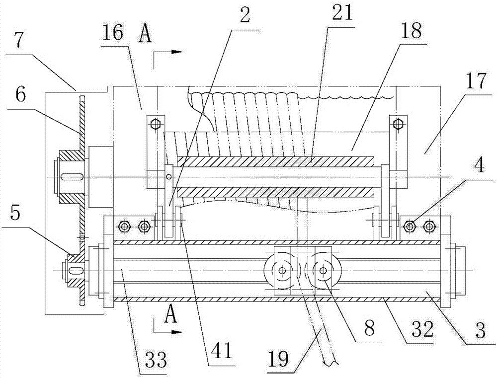
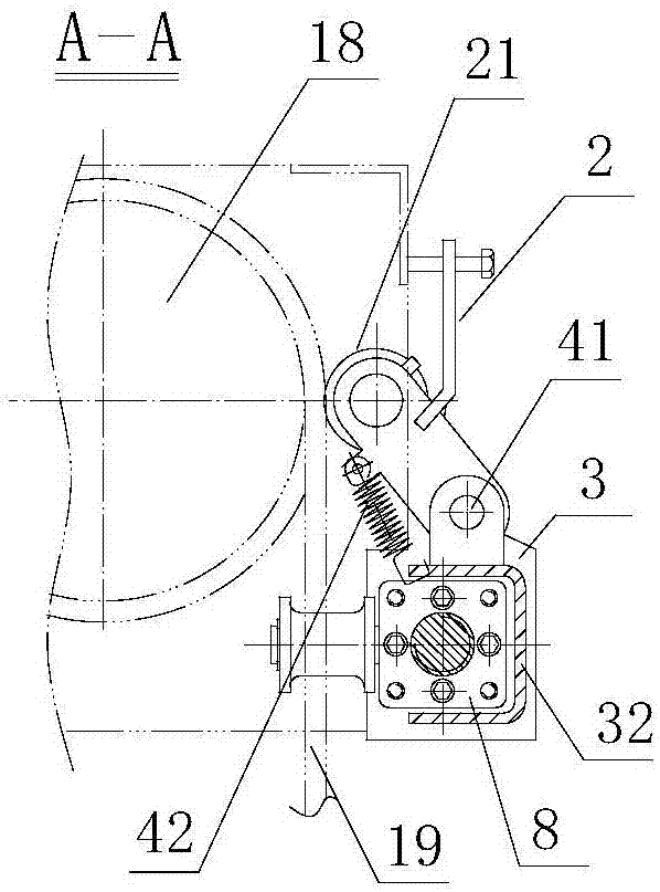
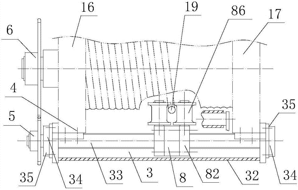
[0019] like figure 1 , figure 2 , image 3 As shown, a rope guide with a sleeve type rope pressing device and a threaded guide mechanism includes a sleeve type rope pressing device 2 and a threaded guide mechanism 3; the sleeve type rope pressing device 2 is connected by a pin 41 On the thread guide mechanism 3, the sleeve-type rope pressing device is connected with the thread guide mechanism through a spring 42; the sleeve 21 on the sleeve-type rope pressing device is pressed on the reel 18 on the steel wire rope; the thread guide mechanism 3 is provided with an adjustable guide rope device 8; the two ends of the thread guide mechanism are respectively connected to the front of the drum outlet by bolts 4; the thread guide mechanism on the One end of the threaded shaft 33 is connected to the pinion 5; the pinion is meshed with the bull gear 6; the bull gear is connected to one end of the reel shaft of the electric hoist; The cover is connected to the shell at the end of the electric hoist.
[0020] The thread guide mechanism 3 includes a threaded shaft 33, an adjustable rope guide device 8, and a guide bracket 32, and the adjustable rope guide device is connected to the threaded shaft 33 by threads; the two ends of the threaded shaft The bearing and the bearing seat 34 are respectively connected; the bearing seat is connected to both ends of the guide bracket 32 ​​by bolts 35 .
[0021] like Figure 4 As shown, the sleeve-type rope pressing device 2 includes a sleeve 21 and a mandrel 22, and the sleeve is connected to the mandrel and is rotatable; connected; the connecting plate is provided with a spring hole 241 and a pin hole 242; the connecting plate is also welded with a limit plate 25, and the limit plate is connected with a limit bolt 26 for adjusting the mandrel and the reel The shafts are parallel and keep the proper gap between the sleeve pipe 21 and the steel wire rope.
[0022] like Figure 5 As shown, the guide bracket 32 ​​includes a U-shaped guide beam 323, and the two ends of the U-shaped guide beam are respectively welded to a left fixed seat 321 and a right fixed seat 322; a bearing hole 3212 and a bearing hole 3212 are arranged on the left fixed seat. The seat connection hole 3211; the right fixed seat is provided with a bearing hole 3222 and a bearing seat connection hole 3221; the back side of the U-shaped guide beam is provided with an adjustment window 3233 for adjusting the screw on the adjustable guide rope device; A pair of hinge seats 3231 are respectively welded at both ends of the U-shaped guide beam, and pin holes 3232 are provided on the hinge seats; spring holes 3233 are provided beside the hinge seats.
[0023] like Image 6As shown, the adjustable rope guide device 8 includes a threaded slider 81, a fixed block 82, an adjustment block 83, and a rope guide wheel 86, and the threaded slider 81 is provided with a threaded hole 811 and a connecting hole 813; The fixed block 82 is provided with a shaft hole 821 and a connecting hole 822, and one surface of the fixed block is connected with a guide wheel shaft A823, and the guide wheel shaft A is connected with a guide wheel 86, and the guide wheel is provided with Rope groove 861; the adjusting block 83 is provided with shaft holes 831 and threaded holes 832, and one surface of the adjusting block is connected with a guide wheel shaft B833, and the guide wheel shaft B is connected with the guide wheel 86; The adjusting block, the threaded slide block and the fixed block are connected by a plurality of screws A84 and screws B85.

PUM

no PUM

Description & Claims & Application Information

We can also present the details of the Description, Claims and Application information to help users get a comprehensive understanding of the technical details of the patent, such as background art, summary of invention, brief description of drawings, description of embodiments, and other original content. On the other hand, users can also determine the specific scope of protection of the technology through the list of claims; as well as understand the changes in the life cycle of the technology with the presentation of the patent timeline. Login to view more.

Similar technology patents

Efficient sludge drying treatment device

PendingCN107335279Anovel structureImprove dehydration efficiency
Owner:ZHENGZHOU UNIV

Air purifier capable of automatically removing dust

Owner:JIANGSU CHUANGLAN SOLAR AIR CONDITIONER

Diaryl benzo pyridine derivative, and preparation and use thereof

InactiveCN101463014Ahigh selectivity indexnovel structure
Owner:FUDAN UNIV

Bactericide composition containing coumoxystrobin with synergistic effect

InactiveCN104430357Anovel structureunique mode of action
Owner:JILIN BADA PESTICIDE

Classification and recommendation of technical efficacy words

  • Strong resistance to cable pull
  • novel structure

Backpack medlar-picking machine

InactiveCN101473731Aeasy to movenovel structure
Owner:CHINA AGRI UNIV

Power storage device and electronic device

ActiveUS20160372717A1high capacitynovel structure
Owner:SEMICON ENERGY LAB CO LTD
Why Eureka
Try Eureka