
Bridge jacking system

A jacking and bridge technology, which is applied in the direction of bridges, bridge construction, erection/assembly of bridges, etc. It can solve the problems of large additional stress on the beam body, difficult to solve the compression of steel support pads, unsafe hidden dangers in the upper structure of the jacking system, etc. , to achieve the effect of ensuring safety

Inactive Publication Date: 2018-01-05
WUXI HOUFA AUTOMATIC EQUIP CO LTD
View PDF6 Cites 4 Cited by
  • Summary
  • Abstract
  • Description
  • Claims
  • Application Information

AI Technical Summary

Problems solved by technology

[0002] During the bridge construction process, for the jacking of continuous girder bridges, it is necessary to control the displacement difference at each pier position (at the apex). With the conventionally configured gap protection system, when the jack is switched to the temporary support during the jacking process, due to the support steel pipe Due to compression deformation and connection gaps, the upper beam body will also sink with the retraction of the jack, and the sinking amount is uncontrollable, that is, the displacement difference of each pier position is also difficult to control, which will generate a large additional stress on the beam body. Therefore, Effective measures need to be taken to ensure the control of the fulcrum displacement during the entire jacking process
[0003] The traditional continuous girder bridge jacking construction is difficult to solve the compression of the steel support system system of the steel support pad, such as the sudden failure of the jack, which will cause unsafe hazards in the jacking system and the upper structure

Method used


Image

  • Bridge jacking system

Examples


Embodiment Construction

[0015] In order to make the purpose and technical solution of the present invention clearer, the technical solution of the present invention will be clearly and completely described below in conjunction with the embodiments of the present invention. Apparently, the described embodiments are some, not all, embodiments of the present invention. Based on the described embodiments of the present invention, all other embodiments obtained by persons of ordinary skill in the art without creative efforts shall fall within the protection scope of the present invention.

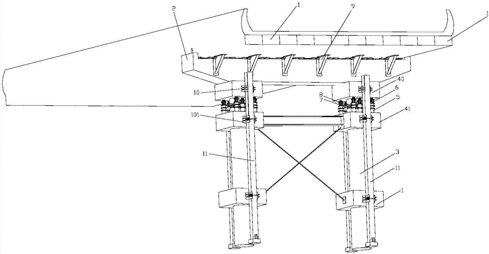
[0016] figure 1 The overall structure of the jacking system of the present invention is shown. The technical features involved in the present invention include plate girder 1, cover beam 2, bridge column 3, upper column-holding beam 40, lower column-holding beam 41, jacking bracket 5, jack 6 , Steel plate pad 7, safety pad 8, connector 9, upper corbel 10, lower corbel 101, I-beam 11, etc.

[0017] Such as figure 1 A...


PUM


Abstract

The invention discloses a bridge jacking system. The bridge jacking system eliminates the compression amount of a steel supporting system at any time through alternate circulative jacking of jack sets, when any one of the jack sets releases pressure, another jack set begins to conduct cylinder stretching jacking, in this way, the problem of altitude difference among supporting points is solved, sothat the displacement of a beam body is in a controllable state. Under each set of supporting states, the compression amount of the supporting system hardly changes, so that the internal force in thebeam body hardly changes, the safety of heavy goods on the upper portion is ensured effectively, and accordingly the structural safety in the jacking process is ensured effectively. The bridge structure being jacked can achieve jacking up, gradient variation, descending and rectifying and the effect that the utilization function of the bridge structure is not reduced after reaching jacking-up according to a program people anticipate.

Description

technical field [0001] The invention relates to the technical field of bridge engineering, in particular to a bridge jacking system. Background technique [0002] During the bridge construction process, for the jacking of continuous girder bridges, it is necessary to control the displacement difference at each pier position (at the apex). With the conventionally configured gap protection system, when the jack is switched to the temporary support during the jacking process, due to the support steel pipe Due to compression deformation and connection gaps, the upper beam body will also sink with the retraction of the jack, and the sinking amount is uncontrollable, that is, the displacement difference of each pier position is also difficult to control, which will generate a large additional stress on the beam body. Therefore, Effective measures need to be taken to ensure the control of the fulcrum displacement during the entire jacking process. [0003] The traditional continuo...

Claims


Application Information

Patent Timeline
Patent Type & Authority Applications(China)
IPC IPC(8): E01D21/00
Inventor 钱国东
Owner WUXI HOUFA AUTOMATIC EQUIP CO LTD
Learn More