

Card edge connector
A card edge connector and card joint technology, applied in the direction of connection, connecting device parts, electrical components, etc., can solve the problem of light guide plate falling off, end wall foolproof grille damage, affecting the light guide effect of the connector light guide plate and other problems to achieve the effect of improving the structural strength
- Summary
- Abstract
- Description
- Claims
- Application Information
AI Technical Summary
Problems solved by technology
Method used
Image

Examples
Embodiment Construction
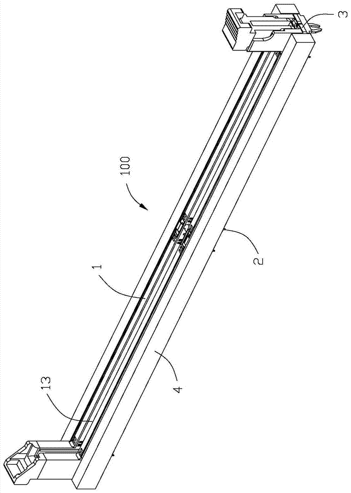
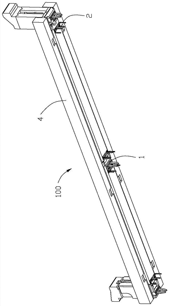
[0031] see figure 1 In the first embodiment shown, the card edge connector 100 of the present invention is mounted on a circuit board (not shown), and the card edge connector 100 is used to insert an electronic card (not shown). The card edge connector 100 includes an insulating body 1 extending in the longitudinal direction, a plurality of conductive terminals 2 accommodated in the insulating body 1, tower-shaped parts 15 located at both longitudinal ends of the insulating body 1, and disposed on the insulating body 1. The metal element 3 outside the insulating body 1 and the light guide plate 4 fixed on the outside of the metal element 3 .
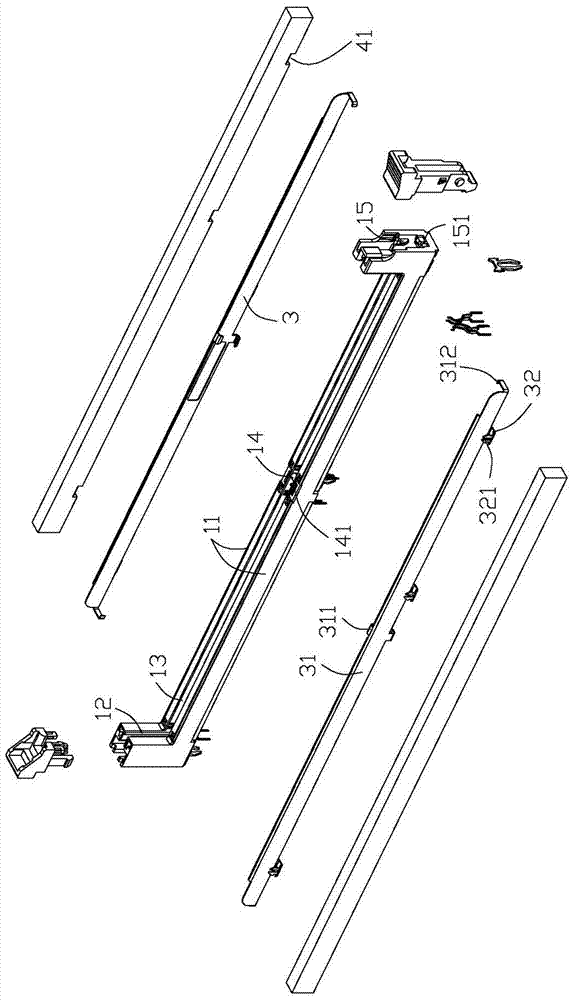
[0032] see Figure 2 to Figure 4 In the first embodiment shown, the insulating body 1 has two parallel side walls 11 extending along the longitudinal direction, two end walls 12 located at the longitudinal end and connecting the side walls 11, and two end walls 12 located at the two sides Between the wall 11 and the two end walls 12 is...
PUM
 Abstract
Description
Claims
Application Information