
Electric power monitoring device based on Ethernet

A technology of power monitoring and Ethernet, applied in the direction of circuit devices, electrical components, etc., can solve problems such as low efficiency, inability to realize power monitoring, and low degree of intelligence

Inactive Publication Date: 2018-01-05
缪建良
View PDF0 Cites 0 Cited by
  • Summary
  • Abstract
  • Description
  • Claims
  • Application Information

AI Technical Summary

Problems solved by technology

At present, the monitoring of the power of ocean-going ships is largely achieved through manual inspection or combined with some detection terminals. Real-time power monitoring cannot be realized, and the efficiency is low and the degree of intelligence is low.

Method used


Image

  • Electric power monitoring device based on Ethernet

Examples


Embodiment Construction

[0011] The present invention will be further described below in conjunction with drawings and embodiments. It should be understood that the specific embodiments described here are only used to explain the present invention, but not to limit the present invention. In addition, it should be noted that, for the convenience of description, only parts related to the present invention are shown in the drawings but not all content. Unless otherwise defined, all technical and scientific terms used herein have the same meaning as commonly understood by one of ordinary skill in the technical field of the invention. The terms used herein in the description of the present invention are for the purpose of describing specific embodiments only, and are not intended to limit the present invention. As used herein, the term "and / or" includes any and all combinations of one or more of the associated listed items.

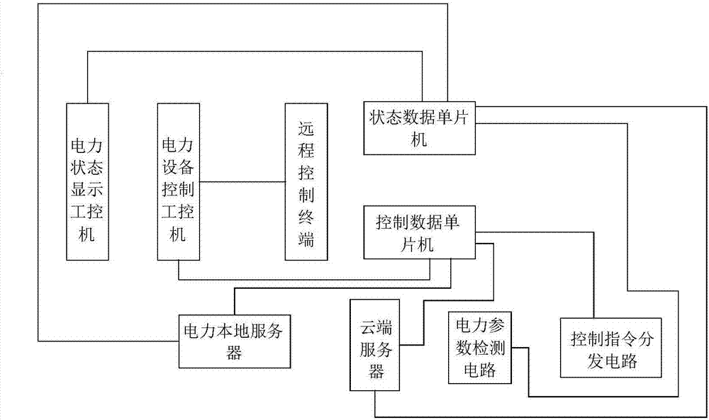
[0012] Please refer to figure 1 as shown, figure 1 The structure diagram of t...


PUM


Abstract

The invention discloses an Ethernet-based power monitoring device, which includes a power state display industrial computer, a power equipment control industrial computer, a state data single-chip microcomputer, a control data single-chip microcomputer, a local power server, a cloud server, a power parameter detection circuit, and a control instruction distribution circuit. The power state display industrial computer is connected to the state data single-chip computer through Ethernet; the power equipment control industrial computer is connected to the control data single-chip computer through Ethernet; the local power server is connected to the state data single-chip computer and the control data single-chip computer through Ethernet; The cloud server is connected to the state data single-chip microcomputer and the control data single-chip microcomputer through the wireless network; the state data single-chip microcomputer is connected to the power parameter detection circuit; the control command distribution circuit is connected to the control command distribution circuit. The invention realizes the connection and control of the monitoring equipment through the Ethernet, and completes the real-time power monitoring of the ship.

Description

technical field [0001] The invention relates to the field of power monitoring, in particular to an Ethernet-based power monitoring device. Background technique [0002] The degree of electrification of modern ships is getting higher and higher, and the dependence on power supply is getting stronger and stronger. Therefore, the power system has become one of the indispensable and important systems of modern ships. The power supply of the equipment must maintain a high quality of power supply under the conditions of complex and changing working conditions. The requirements for the continuity of the power supply of the ship's power distribution system are also getting higher and higher. The requirements for the protection device of the ship's power distribution system are to safely break the overcurrent caused by faults such as short circuits, and at the same time make the scope of the accident as small as possible. Especially for important loads in the ship, the continuity of...

Claims


Application Information

Patent Timeline
Patent Type & Authority Applications(China)
IPC IPC(8): H02J13/00
Inventor 缪建良
Owner 缪建良
Learn More