
Spatial positioning device and method, corrector and correction method

A technology of spatial positioning and spatial position, which is applied in the fields of orthodontics, orthotics, spatial positioning devices and positioning, can solve problems such as undetectable, size error, inconvenient marking positioning, etc., and achieve distance relationship correction, simple calculation method, and applicable wide scene effect

Pending Publication Date: 2018-01-09
SHANGHAI INNOMOTION
View PDF9 Cites 3 Cited by
  • Summary
  • Abstract
  • Description
  • Claims
  • Application Information

AI Technical Summary

Problems solved by technology

[0003] At present, the way to realize the tracking and positioning of three-dimensional position points is usually to set markers directly at the positions that need to be positioned. However, there are some positions that are not convenient for direct marker positioning, such as relatively secluded positions, where markers or markers cannot be set Parts are easily occluded and cannot be detected, so it is necessary to improve the spatial calibration device to spatially locate these positions
[0004] In addition, due to factors such as manufacturing errors, changes in temperature and humidity, or aging, or deformation of the space calibration device, there will be dimensional errors, which cannot guarantee the accuracy of positioning. Therefore, it is necessary to correct the space calibration device, otherwise it can only It was scrapped and remade, and currently there is no better corrector to correct the space calibration device

Method used


Image

  • Spatial positioning device and method, corrector and correction method
  • Spatial positioning device and method, corrector and correction method
  • Spatial positioning device and method, corrector and correction method

Examples


Embodiment Construction

[0052] In order to make the above objects, features and advantages of the present invention more comprehensible, specific implementations of the present invention will be described in detail below in conjunction with the accompanying drawings.

[0053] In the following description, numerous specific details are set forth in order to provide a thorough understanding of the present invention. However, the present invention can be implemented in many other ways different from those described here, and those skilled in the art can make similar extensions without violating the connotation of the present invention, so the present invention is not limited by the specific implementations disclosed below.

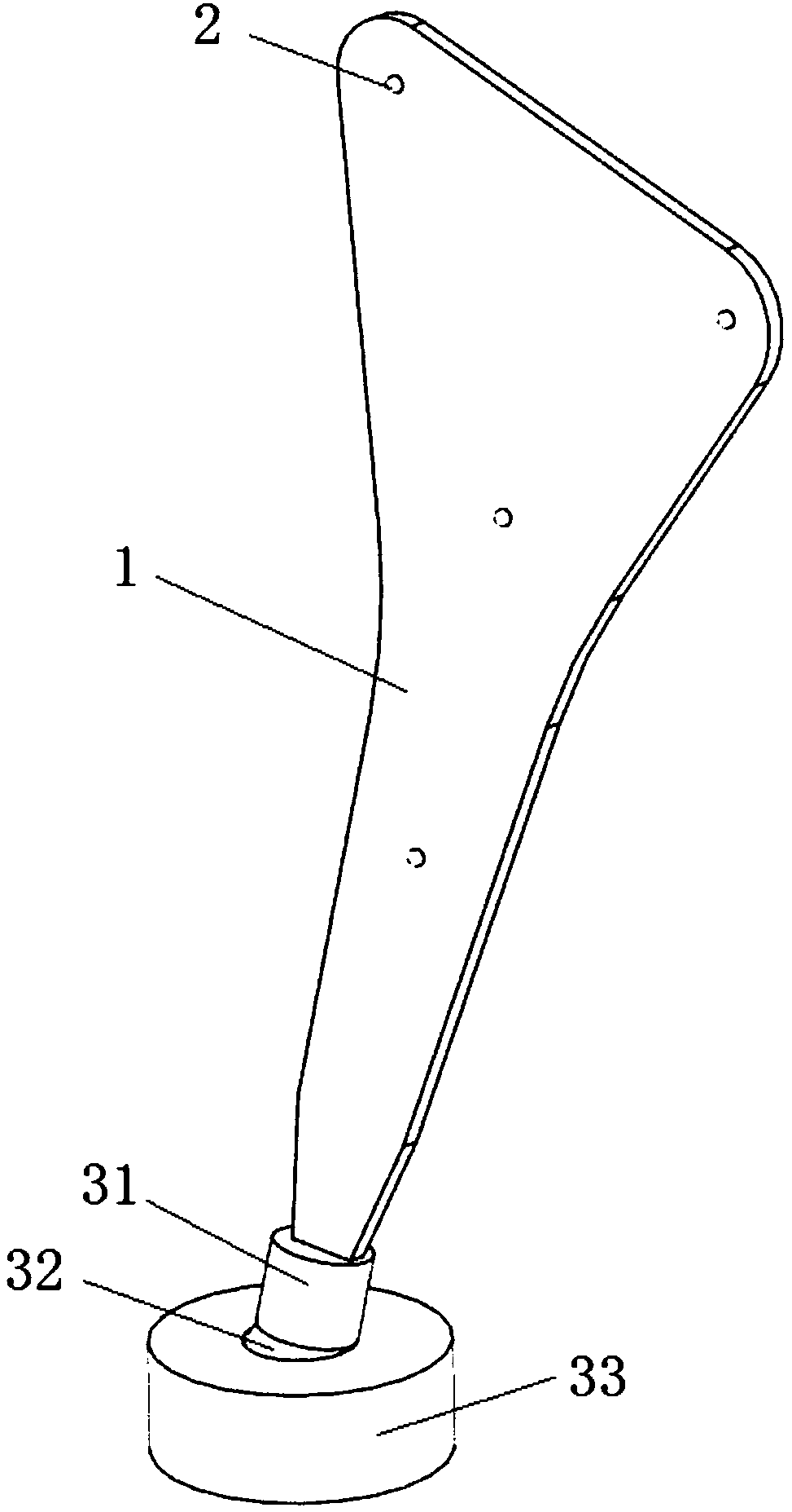
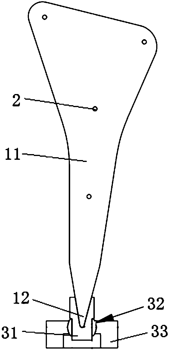
[0054] see figure 1 and figure 2 , The spatial positioning device includes: a board structure 1 and at least three markers 2 . It can be understood that the materials of the marker 2 and the board structure 1 are different, and the marker 2 as a marker on the board structure 1 can ...


PUM


Abstract

The invention provides a spatial positioning device and method, a corrector and a correction method. The spatial positioning device comprises a plate structure and at least three marking members, theplate structure comprises pointed end portions and a marking plate face portion, each marking member is arranged on the marking plate face portion, and intervals among the pointed end portions are different. The spatial positioning device can realize spatial position point positioning when the marking members are inconvenient to place or in the circumstance that spatial position is determined through the marking members and is wider in suitable scene and more convenient.

Description

technical field [0001] The invention relates to the technical field of three-dimensional space position positioning, and in particular to a space positioning device, a positioning method, an orthotic, and an orthotic method. Background technique [0002] In many fields, it is necessary to perform spatial position tracking and positioning on some position points. For example, in the medical field, it is necessary to perform three-dimensional position tracking and positioning on some drilling points, anatomical position points, and feature detection points. After the positioning position is digitalized, subsequent automatic control or data processing can be realized, so it is usually necessary to use a spatial positioning device to achieve position calibration and detection positioning. [0003] At present, the way to realize the tracking and positioning of three-dimensional position points is usually to set markers directly at the positions that need to be positioned. However...

Claims


Application Information

Patent Timeline
IPC IPC(8): A61B90/11A61B90/00
Inventor 王少白张元智兰天蒋文强
Owner SHANGHAI INNOMOTION
Learn More