
A torque limiter for construction electric drill equipment based on slider

A technology of torque limiter and slider, which is applied in the direction of drilling/drilling equipment, mechanical equipment, metal processing equipment, etc., and can solve problems that affect the normal use of the torque limiter and damage the output shaft of the torque limiter.

Active Publication Date: 2018-12-28
山东越浩自动化设备有限公司
View PDF6 Cites 0 Cited by
  • Summary
  • Abstract
  • Description
  • Claims
  • Application Information

AI Technical Summary

Problems solved by technology

[0002] The currently used torque limiter driven by steel balls is continuously increasing with the speed of the input shaft on the torque limiter during use, so that the torque of the output shaft on the torque limiter is also increasing; so that during the use of the torque limiter If the load torque of the output shaft is large at high speed, it may damage the output shaft on the torque limiter; affect the normal use of the torque limiter; so there is a design that can make the output shaft have a lower torque at high speed Torque limiter is very necessary

Method used


Image

  • A torque limiter for construction electric drill equipment based on slider
  • A torque limiter for construction electric drill equipment based on slider
  • A torque limiter for construction electric drill equipment based on slider

Examples


specific Embodiment approach

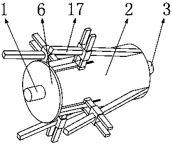
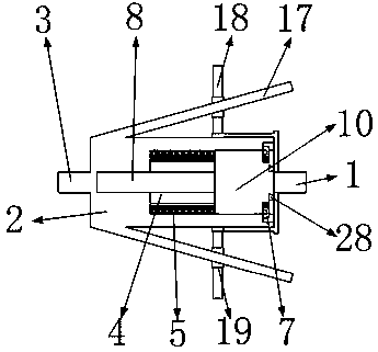
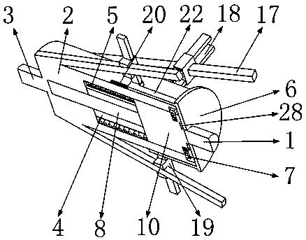
[0039] DETAILED DESCRIPTION OF THE PREFERRED EMBODIMENTS: When people are using the electric drill designed by the present invention, the input shaft 1 rotates, and the input shaft 1 drives the driving ring 10 to rotate; because in the initial state, one end of the four limit trigger blocks 7 is located at four The rotation of the driving ring 10 will drive the drive shell 2 to rotate through the four limit trigger blocks 7; the drive shell 2 drives the output shaft 3 to rotate; that is, the electric drill can be used normally. When the drill bit on the electric drill reaches a high speed during use, in order to prevent the drill bit from breaking, the torque on the drill bit needs to be small in this case, that is, the torque of the output shaft 3 on the torque limiter needs to be adjusted to make it change. When the torque limiter designed by the present invention reaches a certain limit, the limit trigger block 7 installed on the drive ring 10 will move under centrifugal act...


PUM


Abstract

The invention belongs to the technical field of torque limiters, and particularly relates to a torque limiter based on slide blocks and used for building electric drill equipment. The torque limiter comprises an input shaft, a drive shell, an output shaft, drive blades and steel balls. When an electric drill designed by the invention is used by people, the input shaft rotates and drives a drive circular ring to rotate; the drive circular ring rotates to drive the drive shell to rotate through four limit trigger blocks; the drive shell drives the output shaft to rotate; and then the electric drill can be normally used. When a drill bit on the electric drill reaches a high rotating speed during use of the electric drill, the torque on the drill bit needs to be smaller so as to prevent fracturing of the drill bit under the circumstance, that is, the torque on the output shaft of the torque limiter needs to be regulated to be smaller; when the rotating speed of the input shaft of the torque limiter designed by the invention reaches a certain limit, the drive circular ring is disengaged from the drive shell; the drive shell rotates under the effect of friction between the steel balls between the drive shell and a transmission shaft; and the torque of the output shaft can be reduced by regulating the steel balls.

Description

Technical field [0001] The invention belongs to the technical field of torque limiters, in particular to a torque limiter based on a slide block used in construction electric drilling equipment. Background technique [0002] The currently used torque limiter driven by steel balls is continuously increasing with the speed of the input shaft on the torque limiter during use, so that the torque of the output shaft on the torque limiter is also increasing; so that during the use of the torque limiter If the load torque of the output shaft is large at high speed, it may damage the output shaft on the torque limiter; affect the normal use of the torque limiter; so there is a design that can make the output shaft have a lower torque at high speed A torque limiter is very necessary. [0003] The present invention designs a slider-based torque limiter for construction electric drilling equipment to solve the above problems. Contents of the invention [0004] In order to solve the...

Claims


Application Information

Patent Timeline
Patent Type & Authority Patents(China)
IPC IPC(8): B23Q5/58B23Q15/08B25F5/00F16D43/04
CPCB23B45/008B23B45/02B23Q5/58F16D43/04
Inventor 卢洁
Owner 山东越浩自动化设备有限公司
Learn More