Mechanism used for clamping bearing ring

A bearing ring and clamping plate technology, applied in workpiece clamping devices, chucks, manipulators, etc., can solve the problems affecting the quality of the inner or outer wall of the bearing ring, and the inconvenience of clamping the inner or outer ring of the bearing.

Inactive Publication Date: 2018-01-09
SUZHOU RUIDAJU AUTOMATIC EQUIP CO LTD
View PDF0 Cites 11 Cited by
  • Summary
  • Abstract
  • Description
  • Claims
  • Application Information

AI Technical Summary

Problems solved by technology

Existing manipulator grippers for bearings often use mechanical grippers with closed left and right claw blocks. Although this kind of mechanical grippers has good versatility, it is inconvenient to clamp the inner ring or outer ring of the ring-shaped bearing. There are only two p...

Method used


Image

  • Mechanism used for clamping bearing ring
  • Mechanism used for clamping bearing ring
  • Mechanism used for clamping bearing ring

Examples


Embodiment Construction

[0022] The specific implementation manners of the present invention will be further described in detail below in conjunction with the accompanying drawings and embodiments. The following examples are used to illustrate the present invention, but are not intended to limit the scope of the present invention.

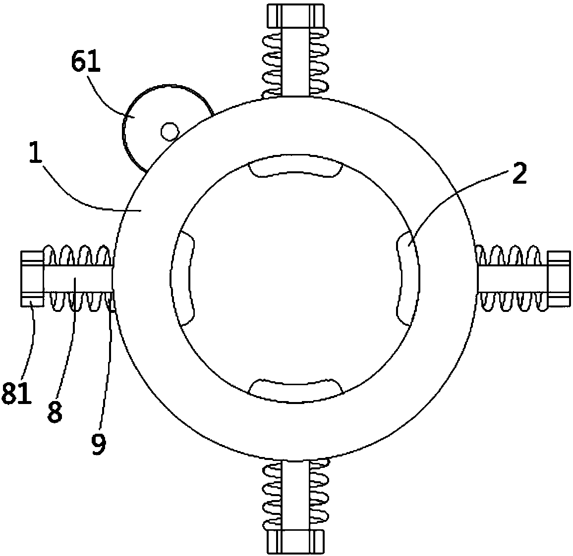
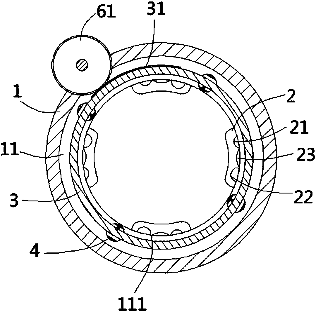
[0023] see Figure 1 to Figure 3 , Figure 5 , a mechanism for clamping bearing rings according to the present invention, including a sleeve 1, the inner wall of the sleeve 1 abuts against a number of arc-shaped clamping plates 2, and the clamping plates in the sleeve 1 There are at least three holding plates 2, and the holding plates 2 are evenly distributed in a ring shape around the central axis of the sleeve 1. The side wall of the holding plate 2 facing the inner wall of the sleeve 1 is formed with a first limiting groove 21 and a second Two limit grooves 22, the first limit groove 21 and the second limit groove 22 are arc-shaped and the depth of the second limit gr...


PUM


Abstract

The invention discloses a mechanism for clamping a bearing ring, which comprises a sleeve, the inner wall of the sleeve abuts against a plurality of arc-shaped clamping plates, and the clamping plates face the side wall of the inner wall of the sleeve A first limiting groove and a second limiting groove are formed on the top, and the first limiting groove and the second limiting groove are both arc-shaped and the depth of the second limiting groove is greater than the depth of the first limiting groove. The first limit groove and the second limit groove are connected by an arc-shaped transition groove. An annular installation groove is formed in the sleeve, and a rotating ring is inserted in the annular installation groove. A corresponding limit ball, the limit ball is against the inner wall of the annular installation groove on one side of the clamping plate, and the outer wall of the rotating ring between the two limit balls is provided with an arc-shaped rack. The arc-shaped rack is meshed with a driving gear, and a compression spring is connected between the limit ball and the rotating ring. The invention can clamp the outer wall of the bearing ring with a small force so as not to damage the bearing.

Description

Technical field: [0001] The invention relates to the technical field of robots for bearing production, in particular to a mechanism for clamping bearing rings. Background technique: [0002] Bearing is a component that fixes and reduces the load friction coefficient in the process of mechanical transmission, and is a widely used component in contemporary mechanical equipment. The existing bearing manufacturing production is gradually changing from manual to fully automated, and robots and manipulators play a vital role in the fully automated production of bearings. Existing manipulator grippers for bearings often use mechanical grippers with closed left and right claw blocks. Although this kind of mechanical grippers has good versatility, it is inconvenient to clamp the inner ring or outer ring of the ring-shaped bearing. There are only two points of contact with the inner ring or outer ring. When the clamping force is small, the friction force is not enough to lift the bea...

Claims


Application Information

Patent Timeline
IPC IPC(8): B25J15/08B25J15/10B25B11/00
Inventor 胡虎
Owner SUZHOU RUIDAJU AUTOMATIC EQUIP CO LTD
Why Eureka
Try Eureka