
Clamp for lens cutting machine

A cutting machine and lens technology, applied in glass cutting devices, manufacturing tools, glass manufacturing equipment, etc., can solve the problems of defective lenses, rework repair, scrapping, etc., and achieve the effect of reducing scratches, reducing defects, and improving surface quality

Pending Publication Date: 2018-01-09
JIANGMEN SHONGLI REARVIEW MIRROR INDAL
View PDF9 Cites 0 Cited by
  • Summary
  • Abstract
  • Description
  • Claims
  • Application Information

AI Technical Summary

Problems solved by technology

[0003] However, the method of pressing the lens from above is likely to cause defects on the surface of the lens, such as scratches, dents or intrusion of impurities, which need to be reworked, repaired or scrapped

Method used


Image

  • Clamp for lens cutting machine
  • Clamp for lens cutting machine
  • Clamp for lens cutting machine

Examples


Embodiment Construction

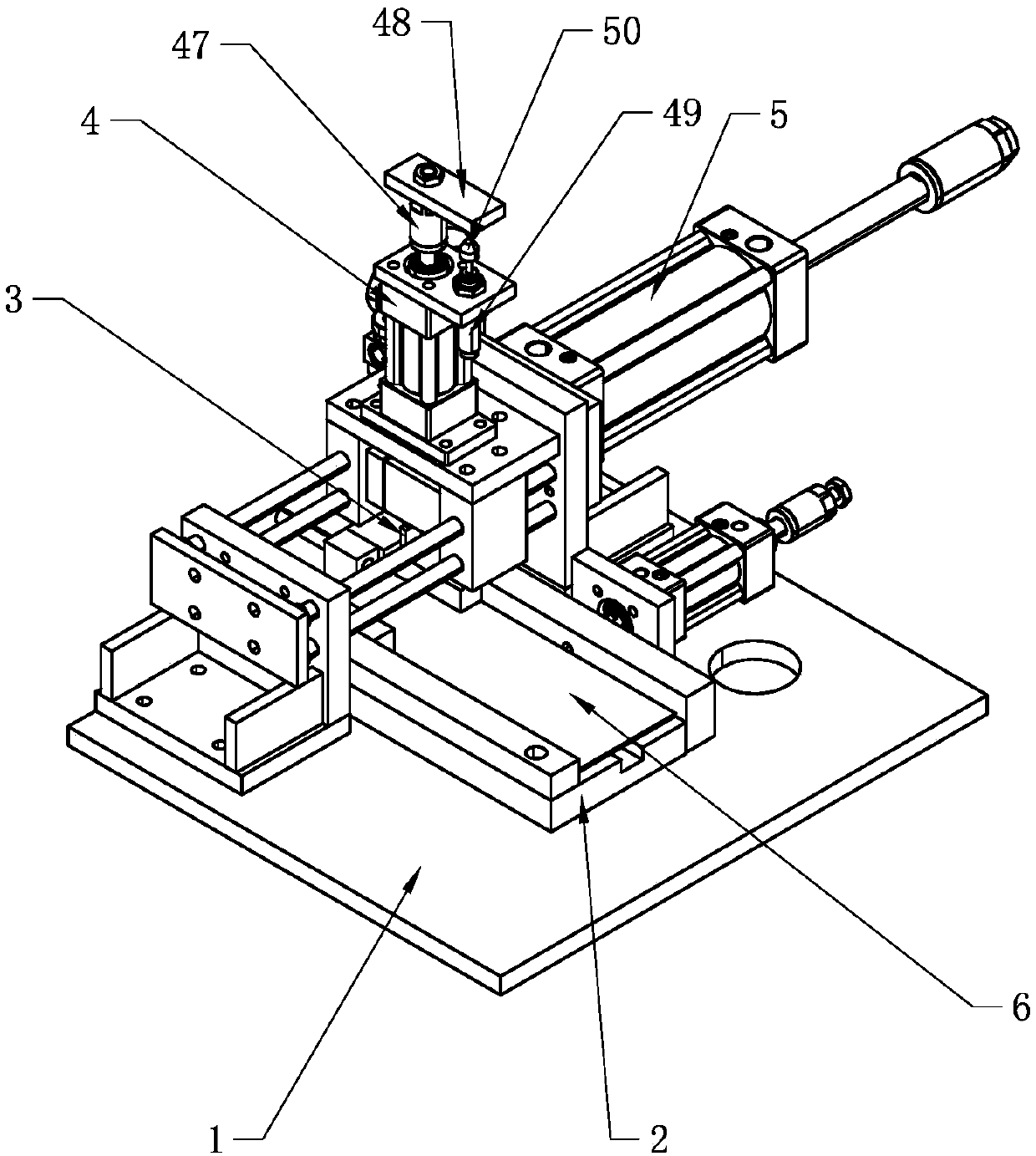
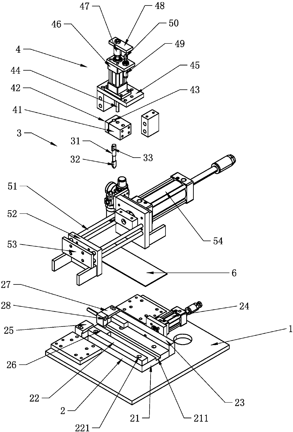
[0021] like figure 1 As shown, a lens cutting machine includes a frame 1, the frame 1 is provided with a clamp 2 for fixing the lens 6, a cutting knife 3, a translation assembly 5 for making the cutting knife 3 approach or move away from the clamp 2, and driving the cutting knife 3 to lift The lifting assembly 4, the cutting knife 3 and the translation assembly 5 are connected through the lifting assembly 4.

[0022] The translation component 5 moves the cutting knife 3 linearly to cut the lens 6 , and the lifting component 4 makes the cutting knife 3 approach and move away from the lens 6 from the vertical direction, so as to avoid repeated cutting of the lens 6 .

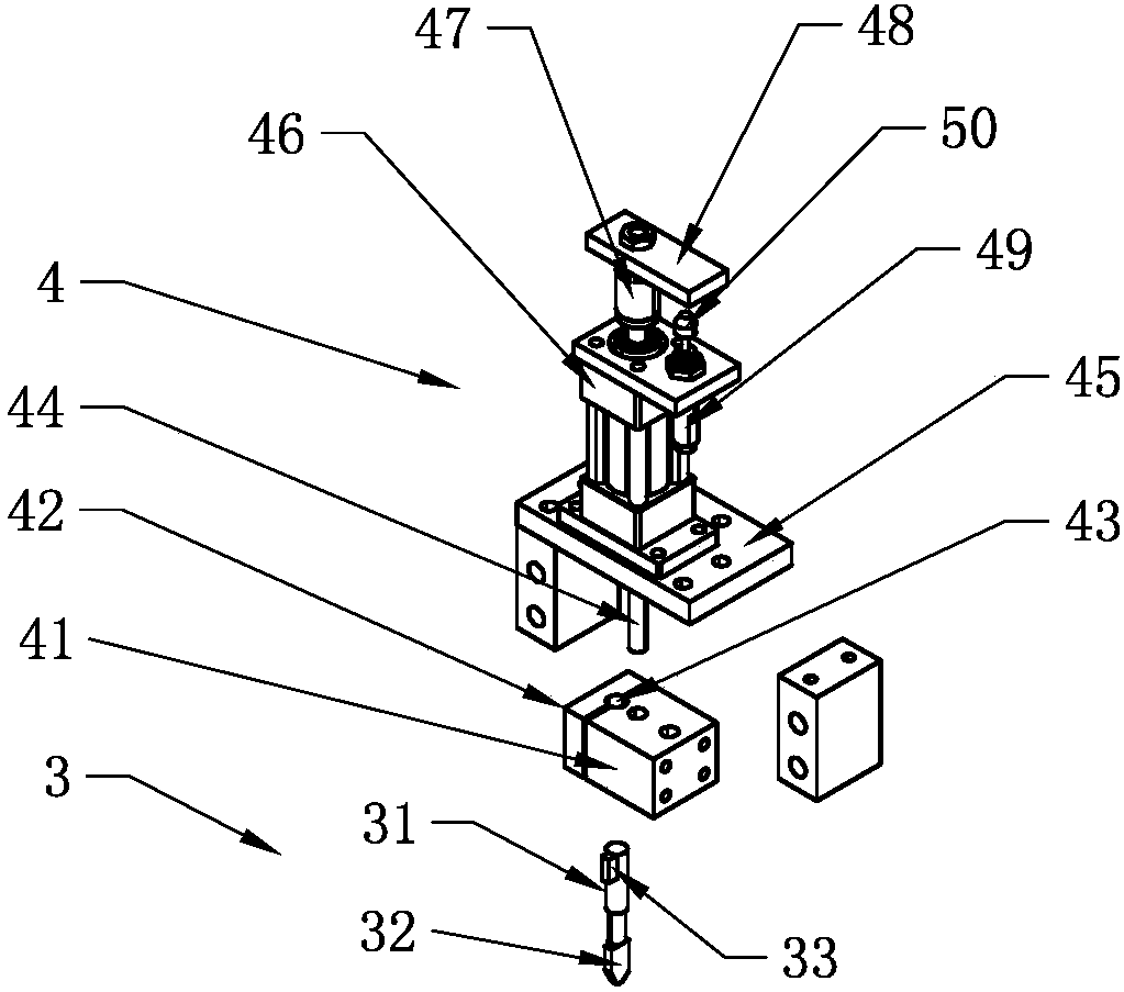
[0023] like figure 2 , image 3 As shown, the cutting knife 3 includes a blade 32 for cutting the lens 6 and a handle 31 connecting the blade 32 , the blade 32 is a common setting, and the handle 31 is provided with a first protrusion 33 that limits the rotation of the handle 31 . The first protrusion 33 can f...


PUM


Abstract

The invention discloses a clamp for a lens cutting machine. The clamp for the lens cutting machine comprises a bottom plate for supporting lenses; and the bottom plate is provided with a first masterplate and a second master plate used for positioning the lenses, a first clamping plate making the lenses fixed to the first master plate or making the first master plate loosen the lenses, and a first power piece driving the first clamping plate to be close to or away from the first master plate. According to the clamp for the lens cutting machine, the lenses are clamped from the side direction of the lenses, and the badness on the surfaces of the lenses is reduced.

Description

technical field [0001] The invention relates to lens processing equipment, in particular to a fixture for a lens cutting machine. Background technique [0002] In the prior art, the lens usually needs to be cut into small pieces first, and then further processed. The existing cutting method is generally to lay the lens flat, and then press the lens from above to keep the lens fixed, and then move the cutting knife along a straight line and The lens applies pressure so that the lens is cut into two pieces. [0003] However, the method of pressing the lens from above is likely to cause defects on the surface of the lens, such as scratches, dents or intrusion of impurities, which need to be reworked, repaired or scrapped. Contents of the invention [0004] The present invention aims to solve the above-mentioned technical problems, and provides a clamp for a lens cutting machine, which can clamp the lens from the side of the lens to reduce defects on the surface of the lens. ...

Claims


Application Information

Patent Timeline
Patent Type & Authority Applications(China)
IPC IPC(8): B26D7/02C03B33/04
CPCY02P40/57
Inventor 李嘉骏甘文杰何萍
Owner JIANGMEN SHONGLI REARVIEW MIRROR INDAL
Learn More