Comb-type multidirectional displacement bridge telescoping apparatus

A multi-directional displacement and telescopic device technology, applied in bridges, bridge parts, bridge construction, etc., can solve the problems of broken fasteners, unsound cleaning system, failure of bolts fixing sliding tooth plates, etc., to prevent tooth skipping Effect

Active Publication Date: 2018-01-09
SHANGHAI EAGLE BRIDGE TECH
View PDF8 Cites 0 Cited by
  • Summary
  • Abstract
  • Description
  • Claims
  • Application Information

AI Technical Summary

Problems solved by technology

In the traditional design, on the one hand, it is often impossible to substantially separate the sliding tooth plate from the concrete. When solving the horizontal force, it may affect the rotation function of the toothed joint. Many designs cannot solve the XYZ axis simultaneously. rotation function
On the other hand, when the sliding tooth plate slides relative to the fixed tooth plate, due to the unsound garbage cleaning system, the garbage between the tooth grooves of the fixed tooth plate will cause warping of the sliding tooth plate after a long time, resulting in the fixed sliding tooth plate If the bolts fail, many unsafe hidden dangers will be caused, and in severe cases, the entire telescopic device will be damaged, endangering traffic safety.
[0003] Although now in order to solve the rotational torque of the sliding tooth plate on the horizontal plane, that is, the rotational force of the Z axis, someone has designed a spherical body on the bottom surface of the sliding tooth plate, and a base for accommodating the spherical body on the top surface of the sliding beam body. Generally, fasteners are used to fasten the bridge surface to solve the X-axis rotational force, but due to the torsional force brought by vehicle movement, it is easy to break the fasteners fixing the base, which cannot be solved well. horizontal force

Method used


Image

  • Comb-type multidirectional displacement bridge telescoping apparatus
  • Comb-type multidirectional displacement bridge telescoping apparatus
  • Comb-type multidirectional displacement bridge telescoping apparatus

Examples


Embodiment 1

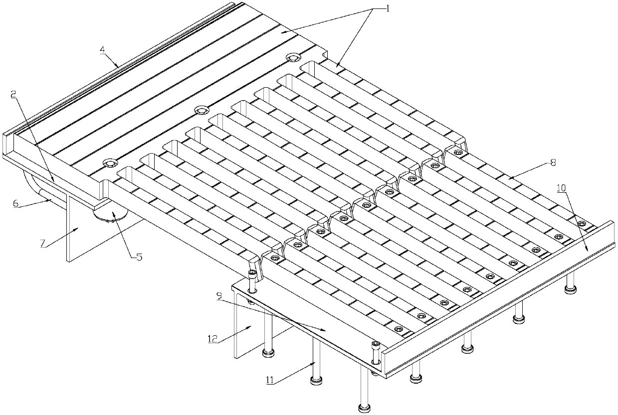
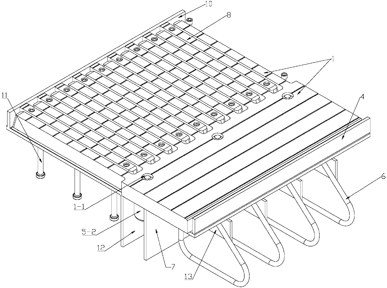
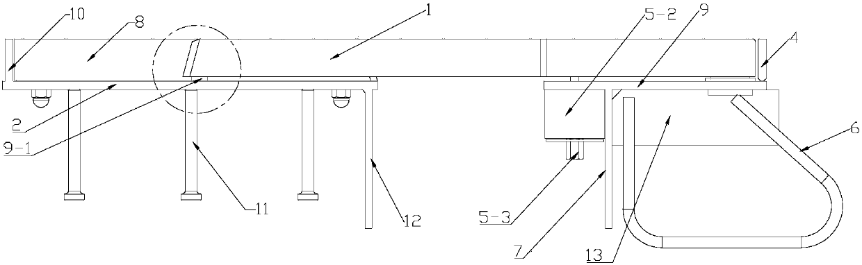
[0036] see Figure 1 to Figure 10 , a comb-tooth type multi-directional displacement bridge telescopic device, comprising a fixed tooth plate, a sliding tooth plate, a fixed beam body, and a sliding beam body. The teeth of the fixed tooth plate 8 are arranged on the fixed beam body 2, so the The comb back of the sliding tooth plate 1 is arranged on the sliding beam body 9. When the sliding tooth plate 1 moves relative to the fixed tooth plate 8, the teeth of the sliding tooth plate 1 and the teeth of the fixed tooth plate 8 are interlaced with each other. :

[0037] The teeth of the fixed tooth plate 8 are bolted on the fixed beam body 2, and the outer end of the fixed beam body 2-1 is provided with a fixed end edge beam 10; 70.

[0038] The sliding tooth plate 1 is connected with the sliding beam body 9 by a rotating shaft device at the comb back away from the tooth portion; and the outer end surface of the sliding beam body 1 is provided with a vertical sliding end edge be...


PUM


Abstract

The invention relates to the bridge dilatation joint technology field, and particularly relates to a comb-type multidirectional displacement bridge telescoping apparatus, wherein, each tooth of a fixed tooth plate is bolted to a fixed beam body; a slide tooth plate is shaft-connected to a slide beam body at the comb back far from the tooth through a rotating shaft apparatus; a gap is left betweena side beam and the slide tooth plate; the slide tooth plate is provided with an elastic straining device between the comb back close to the tooth and the slide beam body for restricting downward displacement of the slide tooth plate and the slide beam body. Compared with prior art, the downward displacement is solved through the relative movement of the slide tooth plate and the fixed beam body;a lower shaft rotates relatively little, which is solved by further compression of a spring; at the same time, the slide tooth plate is pressed on the fixed beam body surface through the spring, preventing jumping gear; furthermore, garbage is removed through a wear resistant-rod arranged under the slide tooth plate, preventing jumping gear caused by the garbage.

Description

technical field [0001] The invention relates to the technical field of bridge expansion joints, in particular to a comb-tooth type multi-directional displacement bridge expansion device. Background technique [0002] With the rapid growth of my country's economy, the span of highway bridges is increasing, and steel box girder has become the mainstream of long-span bridges. Of course, due to temperature, wind, winding deformation, rising or sinking, a certain amount of displacement and rotation will occur. The use of low-noise comb-type multi-directional displacement bridge expansion devices to solve these problems also occupies a certain proportion. In addition to the toothed slot itself adapting to the displacement and rotation of the bridge, and when the vehicle drives on the bridge deck, it will also give a certain X-direction horizontal force to the toothed slot. In traditional designs, on the one hand, it is often impossible to substantially separate the sliding tooth p...

Claims


Application Information

Patent Timeline
Patent Type & Authority Applications(China)
IPC IPC(8): E01D19/06
Inventor 王继化
Owner SHANGHAI EAGLE BRIDGE TECH
Why Eureka
Try Eureka