Eccentric shaft drive mechanism and variable compression ratio mechanism

A drive mechanism and eccentric shaft technology, which is applied in engine control, machine/engine, mechanical equipment, etc., can solve the problems of large size of the drive eccentric shaft, high research and development costs, and complex structure, and achieve simple structure, space saving, and meshing structure. reliable results

Active Publication Date: 2021-09-21
GREAT WALL MOTOR CO LTD
View PDF8 Cites 0 Cited by
  • Summary
  • Abstract
  • Description
  • Claims
  • Application Information

AI Technical Summary

Problems solved by technology

To this end, it is necessary to provide a suitable layout position for the additional power unit, and make major changes to the cylinder block, cylinder head, and crankshaft system of the existing engine. more complex

Method used


Image

  • Eccentric shaft drive mechanism and variable compression ratio mechanism
  • Eccentric shaft drive mechanism and variable compression ratio mechanism
  • Eccentric shaft drive mechanism and variable compression ratio mechanism

Examples


Embodiment 1

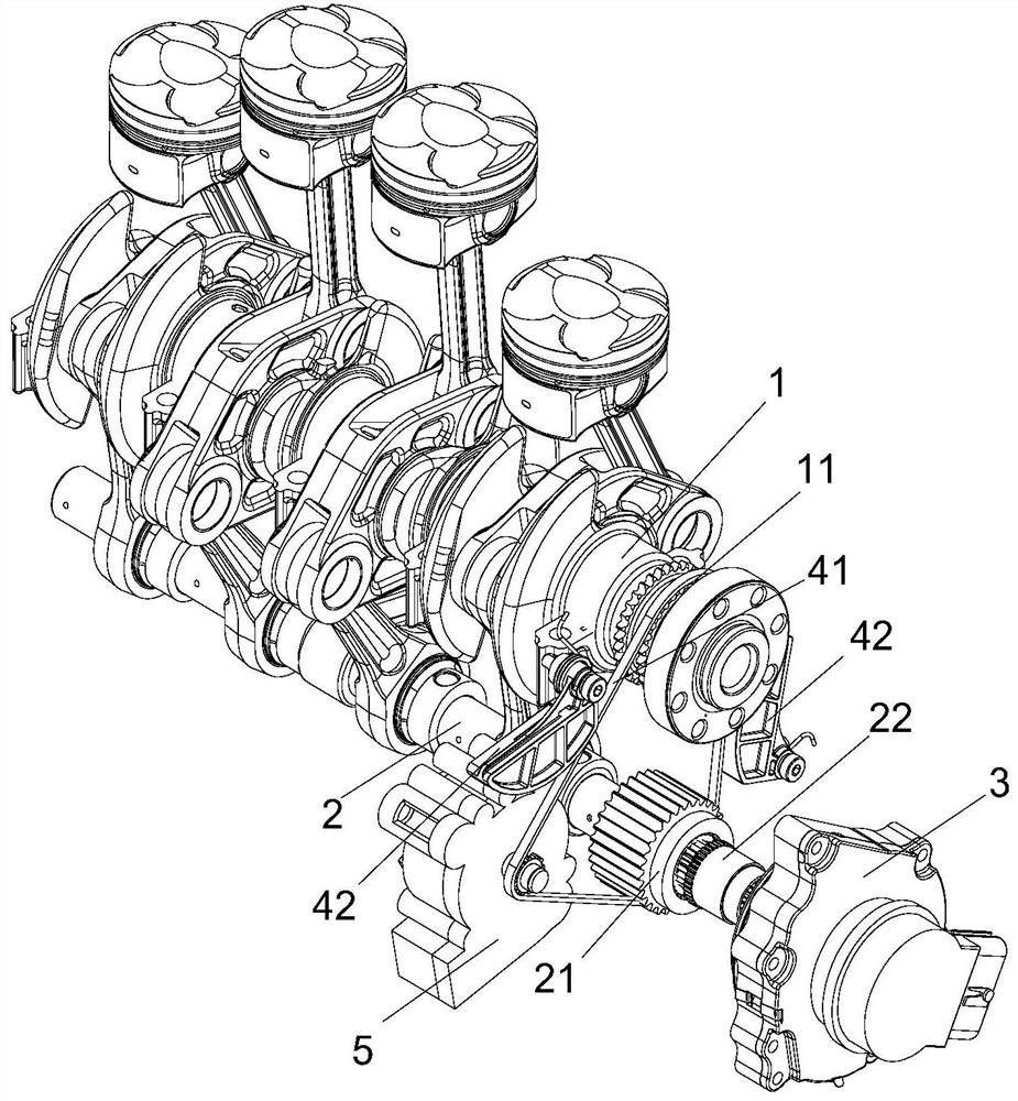
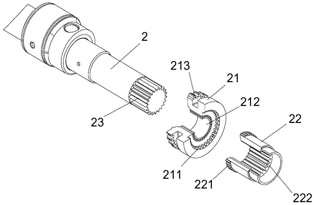
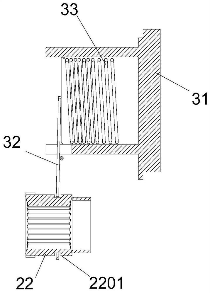
[0037] This embodiment relates to an eccentric shaft driving mechanism, which is used to receive the driving of the crankshaft 1 to drive the eccentric shaft 2 to rotate, such as Figure 1 to Figure 5 As shown, the eccentric shaft drive mechanism includes a follower 21 that is rotatably fitted on one end of the eccentric shaft 2, a transmission member 22 that is sleeved on the eccentric shaft 2 outside the follower 21, and an engine that is fixed to the eccentric shaft 2. The control part 3 on the cylinder body 62 also includes a transmission connection part provided on the transmission part 22 and the follower part 21 .

[0038] Wherein, the follower 21 forms a flexible transmission with the crankshaft 1 through the linkage 41, so that it can rotate synchronously with the crankshaft 1, and the transmission member 22 can slide axially relative to the eccentric shaft 2, and due to the eccentric shaft 2 The meshing connection of the eccentric shaft 2 is synchronously rotated. T...

Embodiment 2

[0049] This embodiment designs a variable compression ratio mechanism, which adopts a multi-link variable compression ratio mechanism, including a piston 61 slidingly arranged in the engine cylinder 62, and a crankshaft assembly arranged in the engine cylinder 62 to rotate. And the eccentric shaft assembly, and the adjusting connecting rod 63 that rotates on the crankshaft 1 in the crankshaft assembly; also includes the execution connecting rod 64 that is hinged between one end of the adjusting connecting rod 63 and the piston 61, and is hinged on the adjusting connecting rod The drive link 65 between the other end of 63 and the eccentric shaft 2 in the eccentric shaft assembly, and the eccentric shaft drive mechanism as described in Embodiment 1.

[0050] In the variable compression ratio mechanism of this embodiment, the eccentric shaft in the eccentric shaft assembly is rotated by the controller of the eccentric shaft drive mechanism as described in Embodiment 1. When the ec...


PUM


Abstract

The present invention provides an eccentric shaft drive mechanism and a variable compression ratio mechanism. The eccentric shaft drive mechanism of the present invention is used to receive the driving of the crankshaft to drive the eccentric shaft to rotate, and it includes a follower that is rotatably fitted on one end of the eccentric shaft. The transmission part sleeved on the eccentric shaft on the outer side of the follower, and the control part fixed on the engine block carrying the eccentric shaft, also includes the transmission connection part arranged on the transmission part and the follower, and the follower Connected with the crankshaft, the transmission part and the eccentric shaft rotate synchronously, and the transmission part can be driven by the control mechanism to be connected or disconnected from the follower, so that the rotation of the crankshaft can drive the eccentric shaft to rotate. The eccentric shaft drive mechanism of the present invention drives the rotation of the eccentric shaft by the rotation of the crankshaft, so that the angle of the eccentric shaft can be changed to achieve the compression ratio of the engine, and the drive mechanism is directly driven by the crankshaft to rotate the eccentric shaft without an external power device. The structure is simple, easy to arrange, and has good practicability.

Description

technical field [0001] The invention relates to the technical field of engine structure, in particular to an eccentric shaft driving mechanism, and also relates to a variable compression ratio mechanism equipped with the eccentric shaft driving mechanism. Background technique [0002] Due to the non-adjustable performance of the connecting rod mechanism of the traditional engine, the piston stroke and the top dead center position of the piston are not changeable, so the compression ratio of the engine machine is also constant, that is, the compression ratio of the engine will not change with the load. In order to take into account power and economy, the compression ratio of the transmission engine will neither be too large nor too small. However, when running at low speed and low speed, the combustible mixture cannot be fully mixed, resulting in low combustion efficiency, high fuel consumption, and insufficient combustion. When the load of the engine is large, knocking is e...

Claims


Application Information

Patent Timeline
Patent Type & Authority Patents(China)
IPC IPC(8): F02B75/04F02D15/02
CPCF02B75/047F02D15/02
Inventor 刘俊杰渠娜刘涛张树旻尹吉杨乐刘君宇张春辉李树会林文段景辉马京卫王红丹
Owner GREAT WALL MOTOR CO LTD
Why Eureka
Try Eureka