
Stroke and compression ratio changing mechanism and control method thereof

A control method and compression ratio technology, applied in engine control, mechanical equipment, machine/engine, etc., can solve the problems of engine thermal efficiency decline, long piston work time, short piston work time, etc., to improve thermal efficiency, ensure long work time, The effect of improving running performance

Pending Publication Date: 2019-11-22
GREAT WALL MOTOR CO LTD
View PDF0 Cites 0 Cited by
  • Summary
  • Abstract
  • Description
  • Claims
  • Application Information

AI Technical Summary

Problems solved by technology

However, due to the invariable compression ratio of traditional engines, only compromise solutions can be adopted for different loads, so that the above effects cannot be obtained.
For the piston stroke, if the expansion stroke is long, the piston will work for a long time, and the engine will do more work. However, due to the existing crank and connecting rod structure, the piston expansion stroke and compression stroke of the traditional engine are the same, so it cannot be made longer
[0003] In order to improve the running performance of the engine under different loads, some automobile manufacturers have proposed a variable compression ratio technical solution. However, this variable compression ratio solution reduces the compression ratio in order to suppress knocking at high loads. However, the expansion ratio of the piston is also reduced, which leads to the short working time of the piston and the decrease of the thermal efficiency of the engine.

Method used


Image

  • Stroke and compression ratio changing mechanism and control method thereof
  • Stroke and compression ratio changing mechanism and control method thereof
  • Stroke and compression ratio changing mechanism and control method thereof

Examples


Embodiment Construction

[0046] It should be noted that, in the case of no conflict, the embodiments of the present invention and the features in the embodiments can be combined with each other.

[0047] The present invention will be described in detail below with reference to the accompanying drawings and examples.

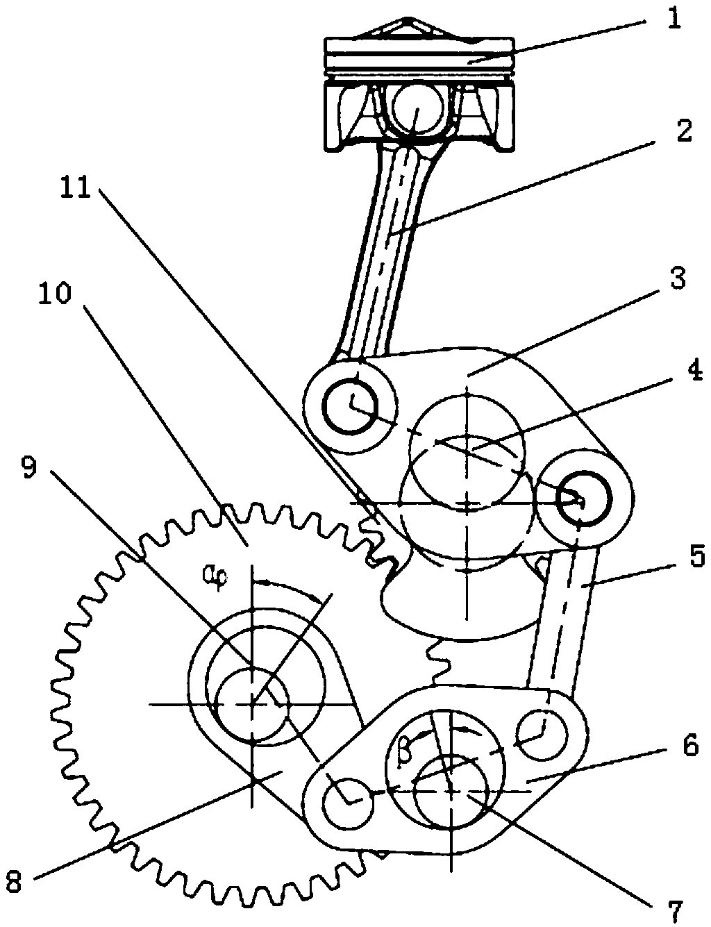
[0048]This embodiment relates to a variable compression ratio mechanism with variable stroke. The variable compression ratio mechanism with variable stroke is controlled by the engine control unit so as to be able to adjust the engine piston stroke and compression ratio, and as figure 1 As shown in , its overall structure includes a piston 1, a crankshaft 4, an eccentric shaft 7, a control shaft 9, and a connecting rod 2, an adjusting connecting rod 3, a driving connecting rod 5 and a swing connecting rod arranged between the above-mentioned components. The multi-link structure formed by the rod 6 and the follower link 8.

[0049] Specifically, the piston 1 is slidably arranged in the c...


PUM


Abstract

The invention provides a stroke and compression ratio changing mechanism and a control method thereof. The stroke and compression ratio changing mechanism is controlled by an engine control unit so asto adjust the piston stroke and compression ratio of an engine; the mechanism comprises a piston, a crankshaft, an eccentric shaft, an adjusting connecting rod, an executing connecting rod and a driving connecting rod, wherein the piston is slidably arranged in an engine cylinder, the crankshaft is rotationally arranged in the engine cylinder, the eccentric shaft is provided with an adjusting eccentric wheel, the adjusting connecting rod is rotationally arranged on a crank of the crankshaft, the executing connecting rod is hinged between one end of the adjusting connecting rod and the piston,and the driving connecting rod is hinged to the other end of the adjusting connecting rod; and the mechanism further comprises a swinging connecting rod, a controlling shaft rotationally arranged inthe engine cylinder and provided with a controlling eccentric wheel, a follow-up connecting rod and an eccentric shaft driving device. According to the stroke and compression ratio changing mechanism,the compression ratio and the piston stroke can be adjusted, and the performance of the engine can be improved.

Description

technical field [0001] The invention relates to the technical field of engines, in particular to a variable compression ratio mechanism with variable stroke, and also relates to a control method of the variable compression ratio mechanism with variable stroke. Background technique [0002] The four strokes of the piston and the compression ratio in the traditional gasoline engine are not variable, and it is difficult to meet the needs of the engine under different working conditions. As for the engine compression ratio, at low load, the compression ratio should be made larger to improve engine thermal efficiency and lower fuel consumption, while at high load, the compression ratio should be made smaller to suppress knocking. However, due to the invariable compression ratio of the traditional engine, it can only adopt a compromise solution for different loads, so that the above-mentioned effects cannot be obtained. For the piston stroke, if the expansion stroke is long, the ...

Claims


Application Information

Patent Timeline
IPC IPC(8): F02B75/04F02D15/02
CPCF02B75/047F02D15/02
Inventor 刘涛林文尹吉刘俊杰张树旻杨乐渠娜刘君宇张春辉李树会段景辉马京卫
Owner GREAT WALL MOTOR CO LTD
Learn More