Driving face local fan remote centralized monitoring device

A technology of tunneling face, centralized monitoring, applied in pump control, mechanical equipment, machine/engine, etc., can solve problems such as power failure and wind failure, threats to mine safety production, no display window for starters, etc., to achieve stable and continuous power supply, Reliable monitoring and alarm, reducing the effect of circuit links

Pending Publication Date: 2018-01-09
SHANXI LUAN ENVIRONMENTAL ENERGY DEV CO LTD WANGZHUANG COAL MINE
View PDF0 Cites 4 Cited by
  • Summary
  • Abstract
  • Description
  • Claims
  • Application Information

AI Technical Summary

Problems solved by technology

Whether the starter is working normally can only be known by the driver who regularly observes the switch. Even some old starters do not have a display window, so it is impossible to judge whether the switch is working normally.
If a power supply circuit or a certain control circuit in the switch fails, and the driver does not find out in time, once the fan cannot be switched automatically, it will easily cause an unplanned power outage and wind stop accident, which poses a threat to the safe production of the mine.

Method used


Image

  • Driving face local fan remote centralized monitoring device
  • Driving face local fan remote centralized monitoring device
  • Driving face local fan remote centralized monitoring device

Examples


Embodiment Construction

[0022] In order to make the purpose, technical solutions and advantages of the embodiments of the present invention clearer, the technical solutions in the embodiments of the present invention will be clearly and completely described below. Obviously, the described embodiments are part of the embodiments of the present invention, rather than All the embodiments; based on the embodiments of the present invention, all other embodiments obtained by persons of ordinary skill in the art without creative work all belong to the protection scope of the present invention.

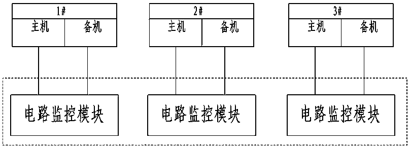
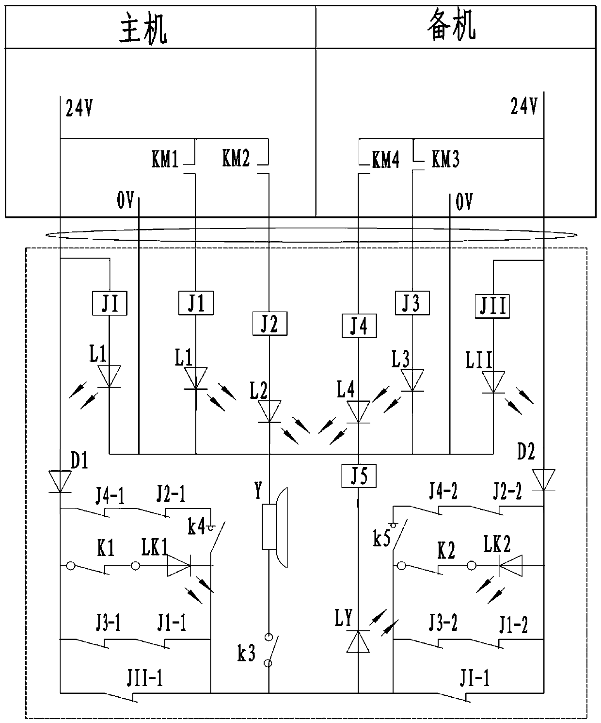
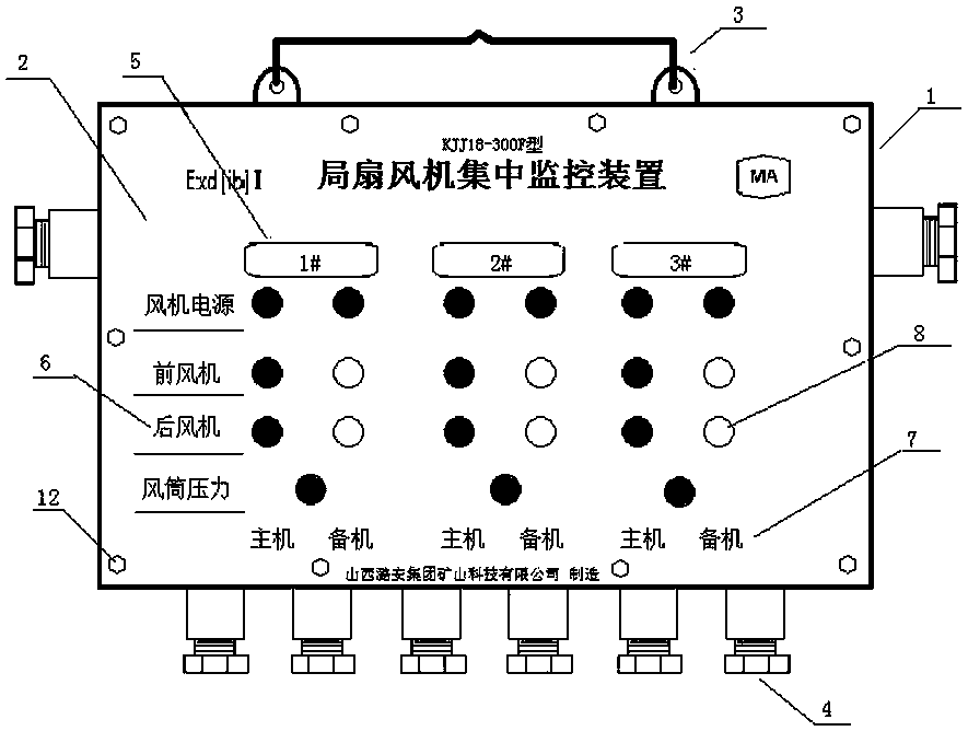
[0023] like Figure 1~4 As shown, it is a long-distance centralized monitoring device for a partial fan fan in the excavation working face proposed by the embodiment of the present invention, such as figure 1 As shown, the circuit of the embodiment of the present invention includes three relatively independent and identical circuit monitoring modules, and these three circuit monitoring modules are arranged in the same...


PUM


Abstract

The invention belongs to the field of coal mining, and provides an underground coal mine local fan remote centralized monitoring device. The underground coal mine local fan remote centralized monitoring device comprises a control circuit box. The control circuit box comprises a shell and a circuit monitoring module. The circuit monitoring module comprises a first relay J1, a second relay J2, a third relay J3, a fourth relay J4, a first loop power monitoring relay JI, a second loop power monitoring relay JII, a first indicator lamp L1, a second indicator lamp L2, a third indicator lamp L3, a fourth indicator lamp L4, a first loop power monitoring indicator lamp LI, a second loop power monitoring indicator lamp LII, a main machine air duct wind pressure indicator lamp LK1, a standby machineair duct wind pressure indicator lamp LK2, a reset switch K3, an audible and visual alarm Y, and a local fan fault alarm indicator lamp LY, wherein the first relay J1, the second relay J2, the third relay J3, the fourth relay J4, the first loop power monitoring relay JI and the second loop power monitoring relay JII are arranged in the shell, and the first indicator lamp L1, the second indicator lamp L2, the third indicator lamp L3, the fourth indicator lamp L4, the first loop power monitoring indicator lamp LI, the second loop power monitoring indicator lamp LII, the main machine air duct wind pressure indicator lamp LK1, the standby machine air duct wind pressure indicator lamp LK2, the reset switch K3, the audible and visual alarm Y and the local fan fault alarm indicator lamp LY are arranged on the surface of the shell. The underground coal mine local fan remote centralized monitoring device can achieve the remote monitoring over the working state of a local fan, and can be widelyapplied to the field of coal mining.

Description

technical field [0001] The invention belongs to the field of coal mining, and in particular relates to a remote centralized monitoring device for a local ventilator in a coal mine. Background technique [0002] Coal mine fully mechanized mining face and various roadway development and excavation rely on local ventilators to provide fresh air flow to the excavation face. The management of underground local ventilators is the first important safety work in coal mines. In order to ensure the reliable, safe and continuous operation of the ventilator, and to prevent unplanned sudden shutdown accidents, in general, it is required to arrange special care for each ventilator. However, the noise produced by the local ventilator is very large, generally above 100-120dB, which greatly exceeds the national noise allowable standard (45-65dB). The high noise not only affects the health of the workers, but also affects the personnel's long-term work. High-intensity noise environments can ...

Claims


Application Information

Patent Timeline
IPC IPC(8): F04D27/00E21F1/08
Inventor 王晓红王伟
Owner SHANXI LUAN ENVIRONMENTAL ENERGY DEV CO LTD WANGZHUANG COAL MINE
Why Eureka
Try Eureka