Test device of module

A test device and test stand technology, applied in the system field, can solve the problem of spending a lot of time, no equipment, a few, as many as dozens, or even hundreds, etc.

Inactive Publication Date: 2018-01-09
天津微贤科技有限公司
View PDF0 Cites 0 Cited by
  • Summary
  • Abstract
  • Description
  • Claims
  • Application Information

AI Technical Summary

Problems solved by technology

[0003] When the current testing tools test the modules in the system, the testers need to constantly open and lock the module casing to debug the module, and the number of screws on the module casing ranges from a dozen to dozens, or even It takes a lot of time to disassemble and assemble the screws, so the traditional debugging method is time-consuming and laborious
[0004] How to improve the existing technology so that it can overcome the above-mentioned problems has become a problem that people generally pay attention to. However, there is no corresponding equipment and no related reports.

Method used


Image

  • Test device of module
  • Test device of module

Examples


Embodiment Construction

[0014] Below, the substantive features and advantages of the present invention will be further described in conjunction with examples, but the present invention is not limited to the listed examples.

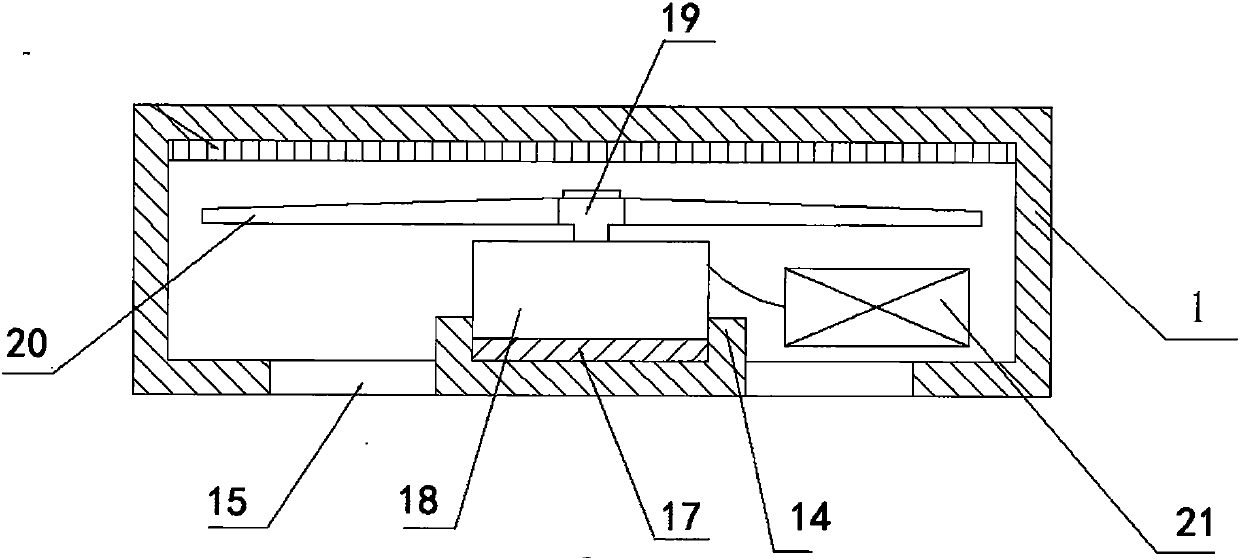
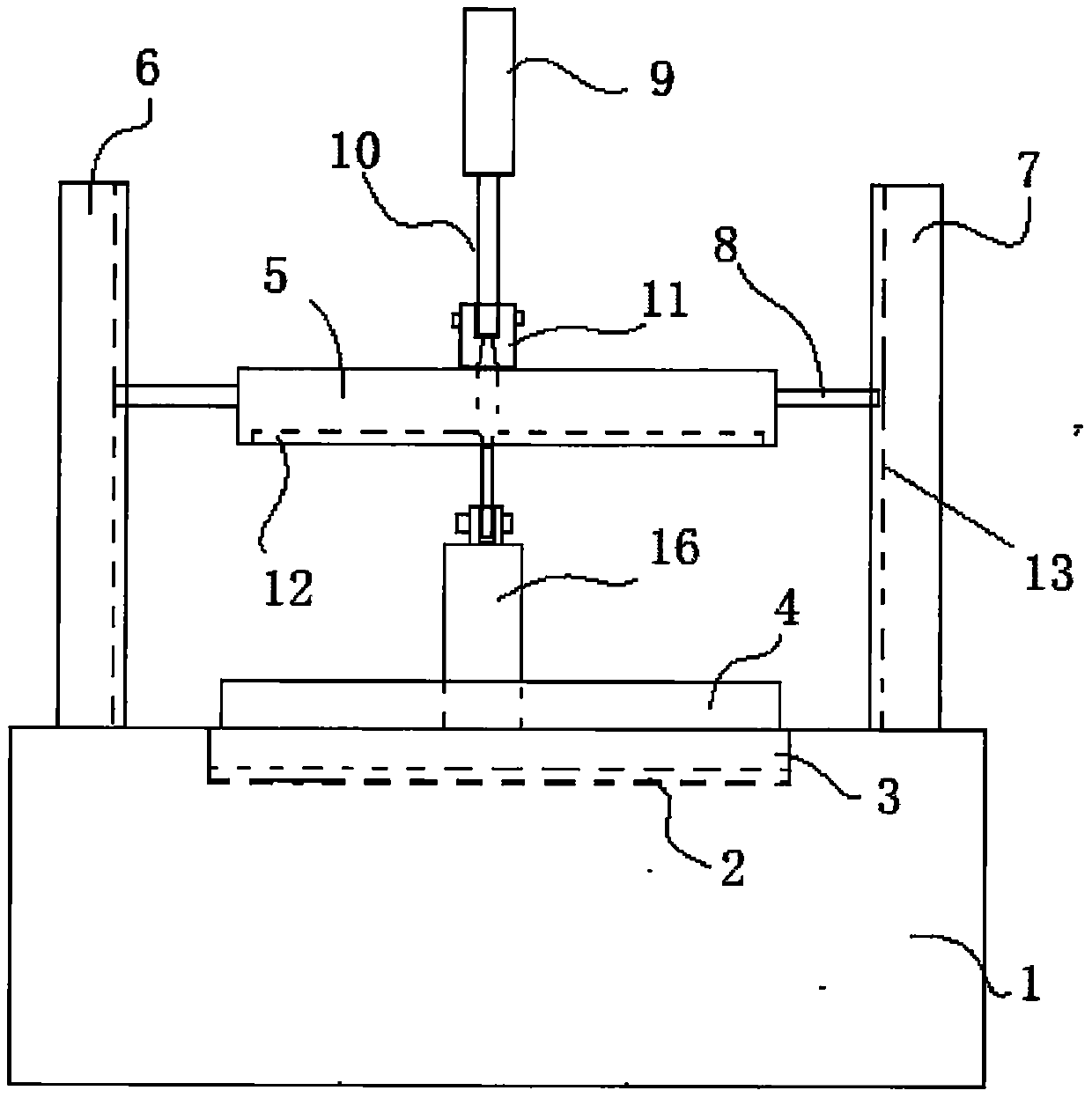
[0015] See Figure 1~2 As shown, a test device for a module includes a test socket 1, a test circuit board 2 matching the module 4 is arranged on the test socket 1, a pressing block 5 is arranged above the test circuit board 2, the The periphery of the pressing surface of the briquetting block 5 has a limit edge 12 matching the shape of the upper end surface of the module shell to form a limit groove, which can cover the upper end of the shell of the module 4. The test seat 1 is provided with a The shape of the bottom end face of the shell of the module is matched with a consistent positioning groove 3, the test circuit board 2 is located in the positioning groove 3, and a heat dissipation system is arranged in the test socket 1, and the heat dissipation system includes The fan...


PUM


Abstract

The invention relates to a module testing device, comprising a test seat, a test circuit board is arranged on the test seat, and a pressing mechanism is arranged above the test circuit board, and the pressing mechanism includes a pressing block. The periphery of the pressure block has a limit edge that matches the shape of the upper end surface of the module shell, and can cover the upper end of the module shell, and the test seat is provided with a positioning groove that matches the shape of the bottom end surface of the module shell; A heat dissipation system is provided in the test seat, and the heat dissipation system includes a fan fixed in the inner cavity of the test seat, the fan is connected to the output shaft of the motor through a rotating shaft, the motor is connected to a battery, and the battery is located in the test seat. In the cavity; the upper part of the cavity is provided with a heat exchanger. The invention does not need to open and lock the module shell to debug the module when testing the module, and has good effect of saving time and effort.

Description

technical field [0001] The invention belongs to the technical field of systems, and in particular relates to a module testing device. Background technique [0002] With the development of science and technology, various modules are used more and more widely, especially in the system, and the quality of the modules also directly affects the quality of the entire system. Therefore, it becomes difficult to test the modules in the system. as important. [0003] When the current testing tools test the modules in the system, the testers need to constantly open and lock the module casing to debug the module, and the number of screws on the module casing ranges from a dozen to dozens, or even It takes a lot of time to disassemble and assemble the screws, so the traditional debugging method is time-consuming and labor-intensive. [0004] How to improve the prior art so that it can overcome the above-mentioned problems has become a problem that people generally pay attention to. How...

Claims


Application Information

Patent Timeline
IPC IPC(8): G01D11/30
Inventor 柴岩岩
Owner 天津微贤科技有限公司
Why Eureka
Try Eureka