Radiator device combination

A technology for radiators and matching parts, applied in the direction of cooling/ventilation/heating transformation, etc., can solve the problems of increased labor costs and high material costs, and achieve the effects of saving space, saving material costs, and balancing pressure

Inactive Publication Date: 2018-01-09
DEYI PRECISION ELECTRONIC IND CO LTD PANYU
View PDF8 Cites 3 Cited by
  • Summary
  • Abstract
  • Description
  • Claims
  • Application Information

AI Technical Summary

Problems solved by technology

[0003] However, this structure requires four sets of screws, nuts and coil springs, and its material cost is relatively high, and it needs to be manually installed four times, resulting in a corresponding increase in labor costs

Method used


Image

  • Radiator device combination
  • Radiator device combination
  • Radiator device combination

Examples


Embodiment Construction

[0027] In order to facilitate a better understanding of the purpose, structure, features, and effects of the present invention, the present invention will now be further described in conjunction with the accompanying drawings and specific embodiments.

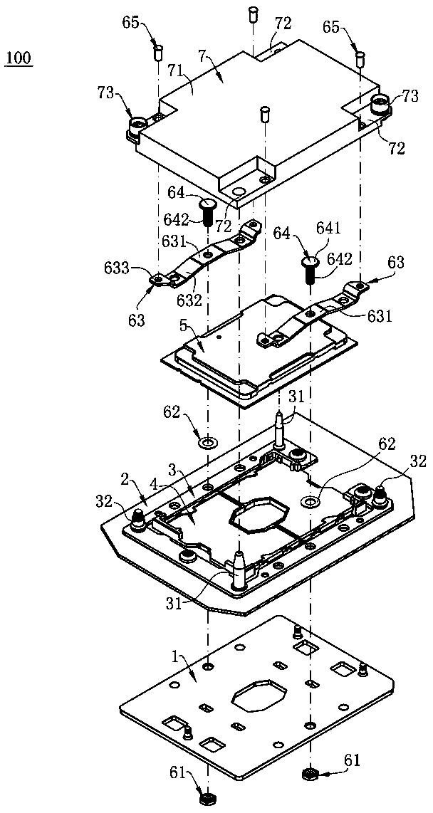
[0028] Such as figure 1 As shown, the radiator device assembly 100 of the present invention mainly includes a metal plate 1, a circuit board 2, a frame body 3, an electrical connector 4, a chip module 5, and two fixing components 6 from bottom to top (auxiliary reference Figure 5 ) and a heat sink 7 .

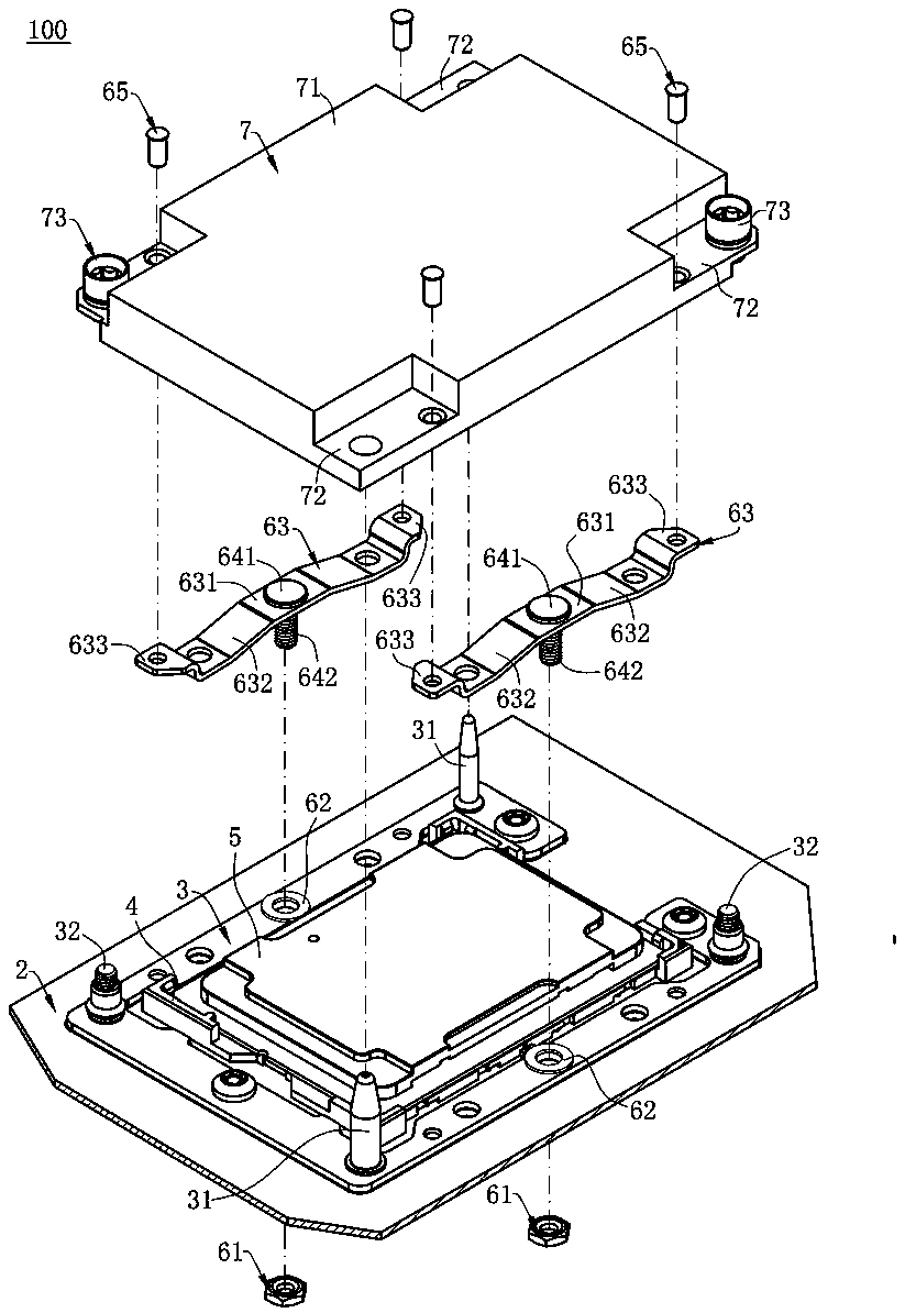
[0029] Such as figure 1 and figure 2 As shown, the metal plate 1 is arranged below the circuit board 2, and the frame body 3 (made of metal material) is arranged above the circuit board 2 and surrounds the electrical connector 4 The metal plate 1 and the frame body 3 clamp the circuit board 2 up and down together, so that the circuit board 2 is not easy to be bent and deformed.

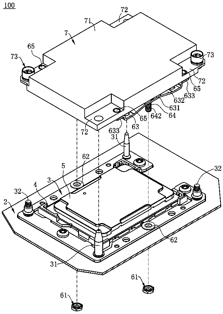
[0030] Such as image 3 As shown, two guid...


PUM


Abstract

The invention discloses a radiator device combination which includes an electrical connector, a chip module disposed on and electrically connected with the electrical connector, a radiator installed above the chip module and used for pressing the chip module, and two fixing components respectively arranged on two opposite sides of the radiator. Each fixing component includes a first locking piece,a second locking piece locked to the first locking piece through threaded fit, and a spring disposed below the radiator. Each spring includes a mating part in the middle and two fixing parts on two opposite sides of the mating part. Each mating part is in contact with the corresponding second locking part. The fixing parts are fixed to the bottom of the radiator. The first locking pieces are prevented by a metal plate from moving upward. When either the first locking pieces or the second locking pieces are rotated until the first locking pieces and the second locking pieces are locked together, the second locking pieces drive the corresponding mating parts to move downward under a downward acting force so that the springs pull down the radiator, and the radiator can well press the chip module.

Description

technical field [0001] The invention relates to a radiator device combination, in particular to a radiator device combination for well-pressed chip modules. Background technique [0002] For example, the Chinese patent No. 201620664550.8 discloses a heat sink assembly, which includes an electrical connector, a chip module on the electrical connector and electrically connected to the electrical connector, a heat sink above the chip module, and Four sets of screws, nuts and helical springs, wherein the helical springs are sleeved on the nuts, and the nuts pass through the radiator downwards and are locked with the screws, so that the radiators elastically press the chip module downwards, so that the chip module abuts against the electric circuit board downwards. The terminals of the connector to ensure good contact between the chip module and the terminals. [0003] However, this structure requires four sets of screws, nuts and coil springs, and its material cost is relativel...

Claims


Application Information

Patent Timeline
Patent Type & Authority Applications(China)
IPC IPC(8): H05K7/20
Inventor 余集晓周彬
Owner DEYI PRECISION ELECTRONIC IND CO LTD PANYU
Why Eureka
Try Eureka