Forging equipment and forging method

A technology for forging and equipment, applied in the field of steel recasting, can solve the problems of huge equipment, low efficiency, and high energy consumption for forging hammer lifting, and achieves the effect of reducing energy consumption, increasing strength, and reducing lifting height.

Inactive Publication Date: 2018-01-12
龙门县南华新金属科技有限公司
View PDF0 Cites 6 Cited by
  • Summary
  • Abstract
  • Description
  • Claims
  • Application Information

AI Technical Summary

Problems solved by technology

Because this kind of forging equipment forms the forging force by the action of gravity, it often needs to adjust its higher height to achieve sufficient forging force, which will make the equipment very large. At the same time, the lifting of the forging hammer requires high energy consumption
and inefficient

Method used


Image

  • Forging equipment and forging method
  • Forging equipment and forging method

Examples


Embodiment 1

[0024] A kind of forging equipment, through the action of gravity and magnetic force to increase the forging strength, and effectively reduce the overall height of the equipment.

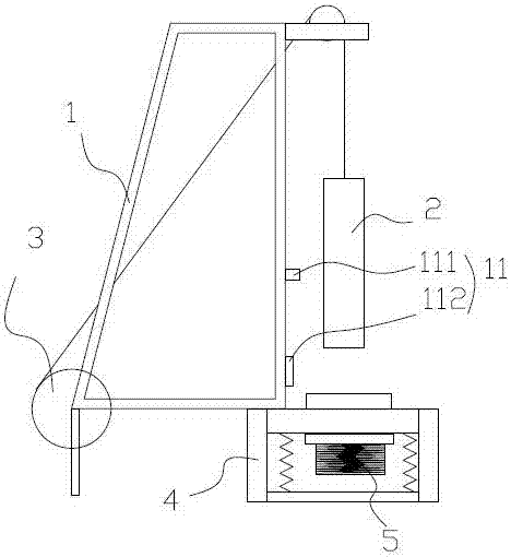
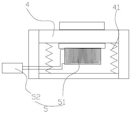
[0025] Specifically, such as figure 1 As shown, including forging frame, forging hammer, driving motor and electromagnetic device.

[0026] Wherein the forging frame is provided with a track for the movement of the forging hammer, the track is placed vertically, and an anvil for forging is provided directly below the track. The forging hammer is set in the track and can move up and down along the forging frame. In order to pull up the forging hammer, the driving motor is also arranged at the bottom of the forging frame, which is connected to the upper end of the forging hammer through a cable. In this embodiment, the top of the forging frame is provided with a fixed pulley, and the cable extends from the motor. It is connected to the top of the forging hammer after bypassing the fixed pulley, and ...

Embodiment 2

[0030] The difference between this embodiment and Embodiment 1 is that this embodiment further includes a trigger device, and the control precision of the electromagnetic device is further improved according to the trigger device.

[0031] Specifically, such as figure 1 shown. The forging frame above the forging anvil is provided with an infrared trigger device, which is connected to send an enable signal to the drive circuit, and the trigger device is turned on and off according to the enable signal. In this embodiment, the infrared trigger device includes a first infrared trigger and a second infrared trigger, the first infrared trigger is arranged above the second infrared trigger, the infrared trigger sends a conduction enable signal to the drive circuit, and the second The infrared trigger sends a disconnect enable signal to the drive circuit.

[0032] During the falling process of the forging hammer, the first infrared trigger will be triggered first, and then the seco...


PUM


Abstract

The invention relates to forging equipment. The forging equipment comprises a forging frame, a forging hammer moving up and down along the forging frame, and a driving motor for driving the forging hammer to move; a forging cutting board and an electromagnetic device are arranged at the bottom of the forging frame corresponding to the forging hammer; the electromagnetic device comprises an electromagnetic coil and a driving circuit; the electromagnetic coil is arranged at the bottom of the forging cutting board and fixedly connected with the forging cutting board; and the driving circuit controls the electrifying state of the electromagnetic coil. In addition, the invention further relates to a forging method; specifically, the forging hammer freely drops down after being lifted to reach aspecific height; and when the forging hammer drops down, the electromagnetic device is controlled to conduct to generate magnetic force so as to improve the forging strength. The forging equipment has the following beneficial effects: (1) the electromagnetic device magnetizes the forging cutting board and a contacted mold, so that the forging strength is improved, the lifting height of the forging hammer is greatly reduced, and the energy consumption is effectively reduced; and (2) the electromagnetic device fixes the forging mold to effectively prevent the technical problem of displacement of the mold in the forging process.

Description

technical field [0001] The invention relates to the field of steel recasting, in particular to forging equipment and a forging method. Background technique [0002] In the existing production process of steel molds, forging is usually inseparable. The forging equipment in the prior art usually adopts the means of gravity forging, and the forging hammer is raised to a certain height to make it fall freely to form A certain impact force, and finally rely on this impact force to complete a forging. Because this kind of forging equipment forms the forging force by gravity, it often needs to adjust its higher height to achieve sufficient forging force, which will make the equipment very large. At the same time, the forging hammer needs to be lifted A lot of energy consumption. And it's also inefficient. Contents of the invention [0003] The object of the present invention is to provide forging equipment and a forging method thereof in order to overcome the defects of the ab...

Claims


Application Information

Patent Timeline
Patent Type & Authority Applications(China)
IPC IPC(8): B21J7/06B21J7/36
Inventor 刘锦秋
Owner 龙门县南华新金属科技有限公司
Why Eureka
Try Eureka