
Conveying device based on vacuum suction cups

A technology of vacuum suction cups and conveying devices, which is applied in the direction of conveyor objects, transportation and packaging, etc. It can solve the problems of affecting the material transportation process, affecting the suction cup adsorption force, suction cup adsorption failure, etc., and achieves improved aesthetics, high work efficiency, and reduced The effect of maintenance costs

Pending Publication Date: 2018-01-12
KUNSHAN TUOYU AUTOMATION TECH CO LTD
View PDF7 Cites 4 Cited by
  • Summary
  • Abstract
  • Description
  • Claims
  • Application Information

AI Technical Summary

Problems solved by technology

In the prior art equipment that uses suction cups to pick and place materials, once the suction cups are adsorbed to the contact surface of the materials, it is difficult to remove the materials, and manual assistance is required to separate the materials from the suction cups, and this type of suction cups will affect the material after repeated use. The adsorption force of the suction cup requires regular replacement of the suction cup, which increases the cost of later maintenance;
[0003] In addition, if there is a little unevenness on the surface of the material, it will cause the suction cup at the low position to complete the adsorption and the suction cup at the high position to fail to absorb, which will seriously affect the material conveying process and reduce the overall work efficiency.

Method used


Image

  • Conveying device based on vacuum suction cups
  • Conveying device based on vacuum suction cups
  • Conveying device based on vacuum suction cups

Examples


Embodiment

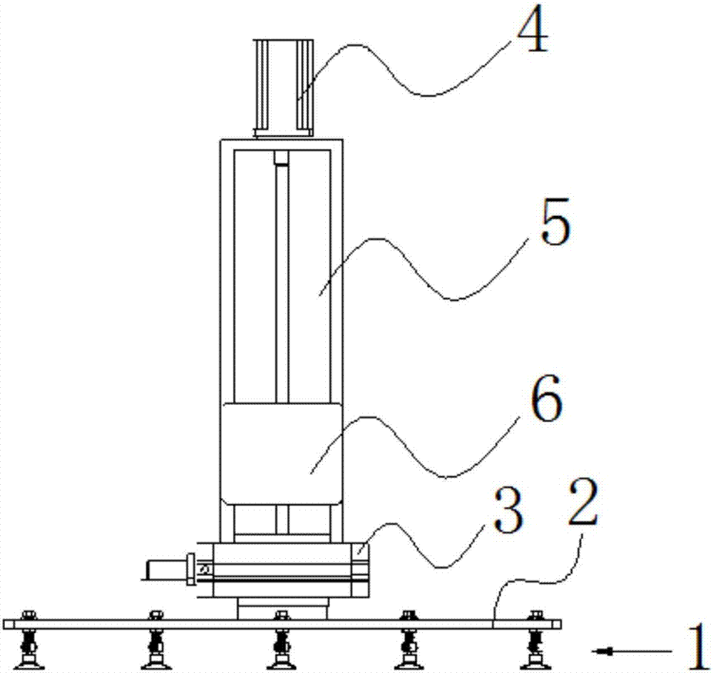
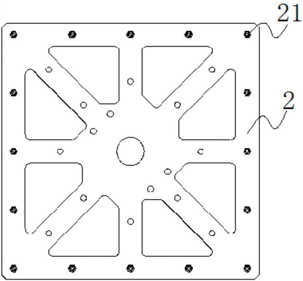
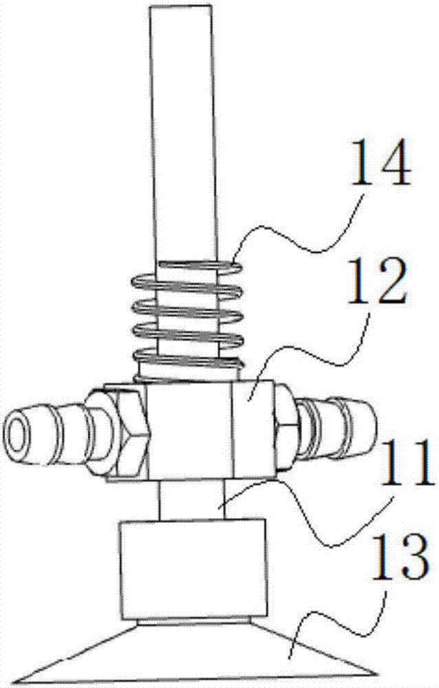
[0028] Embodiment: a kind of conveying device based on vacuum suction cup, as Figure 1-Figure 3 shown, including vacuum cup assembly and delivery assembly;

[0029] The vacuum suction cup assembly includes several vacuum suction cup supports 1 and a suction cup holder 2, and several fixing holes 21 are distributed on the suction cup holder 2, and the upper end of the vacuum suction cup support 1 is detachably connected with the fixing holes 21 ;

[0030] The conveying assembly includes a horizontal rotation mechanism and an up and down movement mechanism; the horizontal rotation mechanism includes a rotary cylinder 3 that can drive the suction cup frame 2 to rotate in the horizontal direction; the up and down movement mechanism includes a motor 4, a screw mandrel 5 and a slider 6 that can move up and down along the screw mandrel 5, one end of the screw mandrel 5 is connected to the output shaft of the motor 4 and the other end is connected to the rotary cylinder 3, and the s...


PUM


Abstract

The invention discloses a conveying device based on vacuum suction cups. The conveying device comprises a vacuum suction cup assembly and a conveying assembly, wherein the vacuum suction cup assemblycomprises a plurality of vacuum suction cup supporting parts and a suction cup frame; a plurality of fixing holes are distributed in the suction cup frame; the upper ends of the vacuum suction cup supporting parts are detachably connected with the fixing holes; the conveying assembly comprises a horizontal rotary mechanism and a vertical moving mechanism; the horizontal rotary mechanism comprisesa rotary cylinder capable of driving the suction cup frame to circumferentially rotate in the horizontal direction; and the vertical moving mechanism comprises a motor, a lead screw and a sliding block capable of moving along the lead screw vertically, one end of the lead screw is connected with an output shaft of the motor, the other end of the lead screw is connected with the rotary cylinder, and the sliding block is fixedly connected with a connection arm. The conveying device is simple in structure, stable in absorption force, and capable of conveniently and rapidly absorbing and conveyingmaterials and improving the work efficiency.

Description

technical field [0001] The invention belongs to the technical field of material pick-and-place, in particular to a conveying device based on a vacuum suction cup. Background technique [0002] The suction cup is a tool that uses the difference in atmospheric pressure between the inside and outside to absorb materials. In the prior art equipment that uses suction cups to pick and place materials, once the suction cups are adsorbed to the contact surface of the materials, it is difficult to remove the materials, and manual assistance is required to separate the materials from the suction cups, and this type of suction cups will affect the material after repeated use. The adsorption force of the suction cup requires regular replacement of the suction cup, which increases the cost of later maintenance; [0003] In addition, if there is a little unevenness on the surface of the material, it will cause the suction cup at the low position to complete the adsorption and the suction...

Claims


Application Information

Patent Timeline
Patent Type & Authority Applications(China)
IPC IPC(8): B65G47/91
Inventor 龚德平吴涛
Owner KUNSHAN TUOYU AUTOMATION TECH CO LTD
Learn More