Vapor deposition apparatus and evaporation source

An evaporation source and evaporation technology, which is applied in the directions of vacuum evaporation plating, sputtering plating, ion implantation plating, etc., can solve the problem of blockage of the opening of the evaporation mouth, and achieve the effect of preventing reflection or re-evaporation

Active Publication Date: 2018-01-12
CANON TOKKI CORP
View PDF4 Cites 1 Cited by
  • Summary
  • Abstract
  • Description
  • Claims
  • Application Information

AI Technical Summary

Problems solved by technology

Deposits on the cooling member are difficult to re-evaporate and grow grad

Method used


Image

  • Vapor deposition apparatus and evaporation source
  • Vapor deposition apparatus and evaporation source
  • Vapor deposition apparatus and evaporation source

Examples


Embodiment Construction

[0033] The action of the present invention is shown based on the drawings, and the preferred embodiments of the present invention are briefly described.

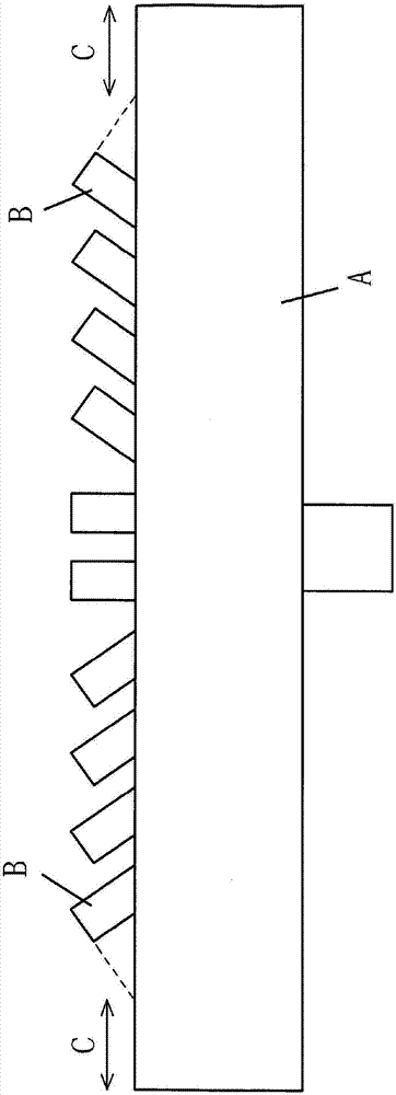
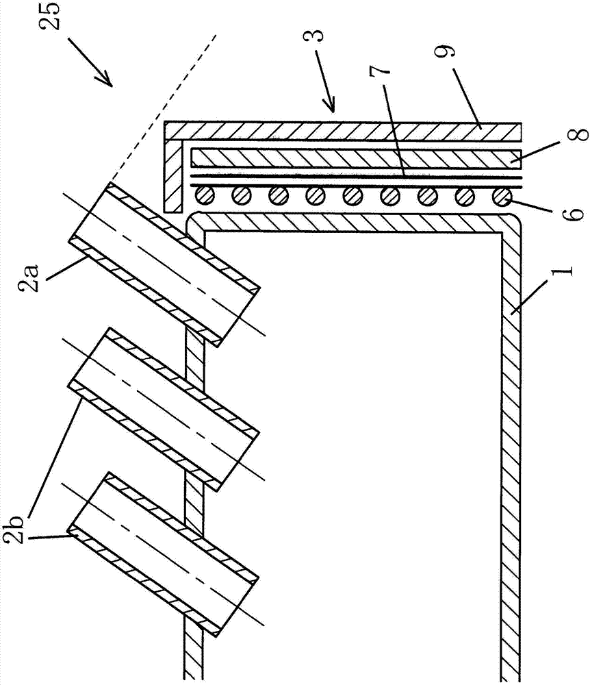
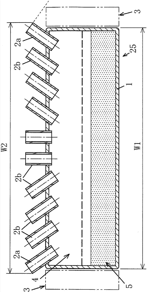
[0034] The evaporated film-forming material is released from the evaporation ports 2a and 2b of the container 1 to form a vapor-deposited film on the substrate.

[0035] At this time, the evaporation source surrounding members 3 such as the container 1 and the heating member and the cooling member do not protrude outward from a virtual plane including the opening end surface of the outer evaporation port portion 2a, that is, they do not protrude outward from the opening end surface of the outer evaporation port portion 2a. There are no container 1 and evaporation source peripheral member 3 in the region affected by the discharged film-forming material, so reflection to the container 1 or re-evaporation of the film-forming material discharged from the opening end surface of the outer evaporation port 2a and to the evaporation ...


PUM


Abstract

To provide a structure capable of preventing reflection or re-evaporation of a film forming material to an evaporation source and deposition on a member around the evaporation source, even in a configuration in which the open end face of the evaporation bulge portion located at the outermost side is inclined to the outside in the long-edge direction of the evaporation source, the invention provides a vapor deposition apparatus and an evaporation source. The vapor deposition device includes an evaporation source having a container (1) for storing a film forming material, a plurality of evaporation ports (2a, 2b) provided in the long edge direction of the container (1), and an evaporation source surrounding member (3) arranged around the container (1), wherein a pair of outer evaporation ports (2a) provided on the outermost side of the plurality of evaporation ports (2a, 2b) have open end faces which are inclined to the outer side in the long edge direction of the container (1). The container (1) and the evaporation source surrounding member (3) are configured so as to enter the inside of the virtual plane without protruding outwardly relative to the virtual plane including the openend faces.

Description

technical field [0001] The invention relates to an evaporation device and an evaporation source. Background technique [0002] In Japanese Patent Application No. 2014-265981, which was previously applied by the applicant himself, a vacuum evaporation device is proposed, which evaporates the outside of the plurality of evaporation ports provided in the evaporation source. The opening end face of the mouth portion is inclined so as to face outward in the longitudinal direction of the evaporation source, thereby, even if the evaporation mouth portion is not arranged so as to expand outward in the longitudinal direction, uniform film thickness distribution can be obtained and the after-effect of film formation can be suppressed. The film in the pattern is blurred by the vapor-deposited film. [0003] However, when the opening end surface of the evaporation port B of the evaporation source A is inclined so as to face outward in the longitudinal direction of the evaporation sourc...

Claims


Application Information

Patent Timeline
IPC IPC(8): C23C14/24
CPCC23C14/243C23C14/24C23C14/225C23C14/564C23C14/12
Inventor 田村博之
Owner CANON TOKKI CORP
Why Eureka
Try Eureka