Electric transmission device of split helicopter tail inclined beam pin locking mechanism and pin locking mode

A transmission device and helicopter technology, applied in transmission devices, motor vehicles, gyrocopters, etc., can solve the problems of optimization, manual manual unlocking, and the locking force cannot be too large, and achieve the effect of reducing risks.

Active Publication Date: 2018-01-12
CHONGQING UNIV +1
View PDF6 Cites 1 Cited by
  • Summary
  • Abstract
  • Description
  • Claims
  • Application Information

AI Technical Summary

Problems solved by technology

However, considering the use and maintenance of the system, the force of manual unlocking and locking should not be too large in the event of a fault. Therefore, how to optimize the braking force and manual torque is a difficult point in the design.

Method used


Image

  • Electric transmission device of split helicopter tail inclined beam pin locking mechanism and pin locking mode
  • Electric transmission device of split helicopter tail inclined beam pin locking mechanism and pin locking mode
  • Electric transmission device of split helicopter tail inclined beam pin locking mechanism and pin locking mode

Examples


Embodiment 1

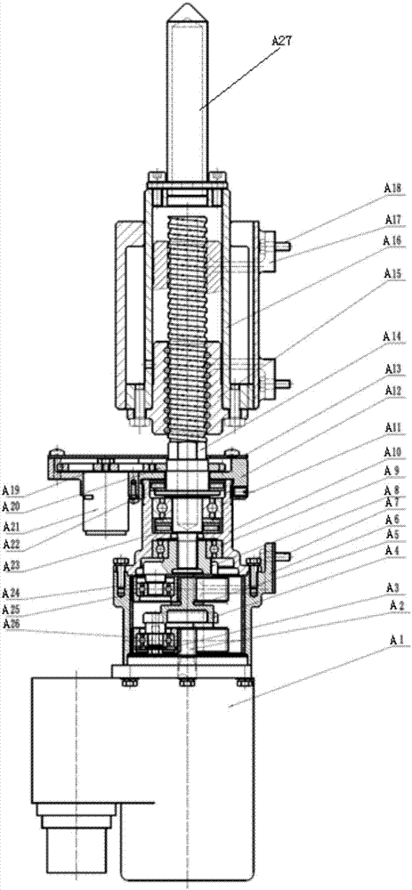
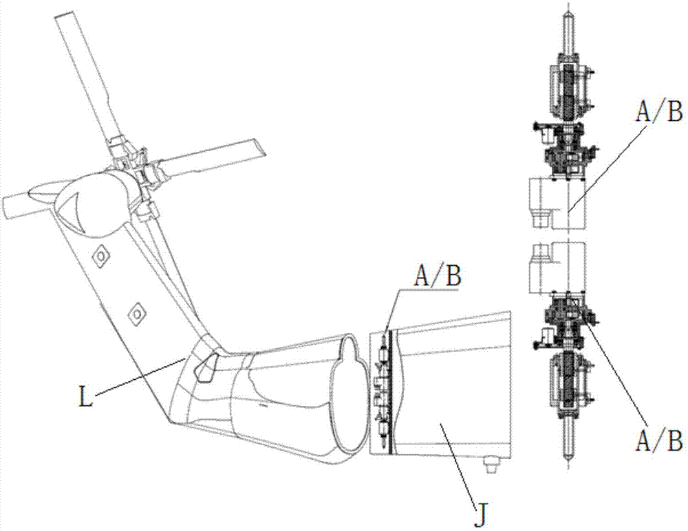
[0037] see figure 1 , a split-type helicopter tail beam locking mechanism electric transmission device, is characterized in that: comprise upper and lower two sets of locking systems A installed on the fuselage J. The locking pins A27 of the two sets of locking pin systems A are retractable, and are used for locking the foldable tail beam L of the helicopter.

[0038] A lock pin system A mainly includes a drive motor A1, a gear transmission reduction pair and a ball screw transmission pair.

[0039] The gear transmission reduction pair includes a two-stage planetary gear train:

[0040] The first-stage planetary gear train is composed of sun gear IA2, ring gear A6, several planetary gears IA3, several deep groove ball bearings IA26 and planet carrier IA4.

[0041] The lower end of the inner ring gear IA6 is fixedly connected with the casing of the drive motor A1 through bolts. The motor output shaft A2 of the driving motor A1 extends into the ring gear IA6, and the upper en...

Embodiment 2

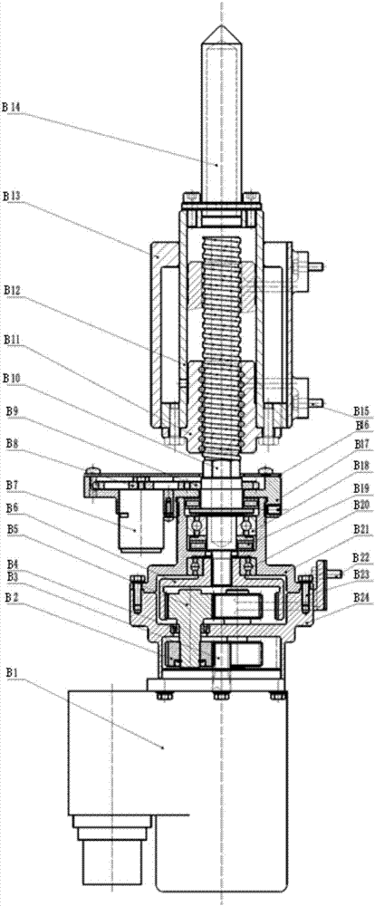
[0047] see figure 2 , a split type helicopter tail beam lock pin mechanism electric transmission device, it is characterized in that: comprise upper and lower two sets of lock pin systems B installed on fuselage J. The locking pins B14 of the two sets of locking pin systems B are retractable, and are used for locking the foldable tail beam L of the helicopter.

[0048] A lock pin system B mainly includes a star gear train and a box

[0049] Described box body is made up of upper box body B21 and lower box body B24. The star gear train is installed inside the box.

[0050] The external meshing transmission of the star gear train is composed of a sun gear IB3 and several planetary gears IB2. The internal meshing of the star gear train is composed of the ring gear IIB6 and several planetary gears IIB5. Each of said planetary gears IB2 is coaxial with a planetary gear IIB5. The coaxially connected planetary gear IB2 and planetary gear IIB5 rotate with the shaft, and their ro...


PUM


Abstract

The invention provides an electric transmission device of a split helicopter tail inclined beam pin locking mechanism and a pin locking mode. Firstly, the rotating speed of a motor is lowered througha gear transmission pair to achieve the purposes of reducing the speed and increasing the torque; and finally, the torque is converted to the linear thrust of a pin locking nut through a ball screw pair to realize quick locking and unlocking of a tail inclined beam. meanwhile, the use and the maintenance of the device are considered; and under the condition of failures, the manual locking and unlocking can be realized. The pin locking device adopts upper and lower sets of split pin locking devices; and each motor drives one locking pin, so that each locking pin can be singly acted to reduce the task risk. The vibration of the tail inclined beam of a helicopter can be effectively reduced in flight, so that the abnormal actions of the tail inclined beam due to vibration are prevented, the guarantee time before and after flight is shortened, and the unfolding and folding reliability of the tail inclined beam of the helicopter is improved.

Description

technical field [0001] The invention belongs to aerospace devices, and in particular relates to an electric transmission device of a split-type helicopter tail beam locking mechanism and a locking method thereof. Background technique [0002] In order to reduce the overall size of the ship-borne helicopter when the whole machine is parked, effectively reduce the storage space of the helicopter on the ship, reduce the support time before and after the flight, and facilitate the take-off and landing of other helicopters, the tail beam of the helicopter must be able to quickly fold and unfold. Ability. In order to ensure flight safety, the tail boom of the helicopter should be locked during flight. The tail boom vibrates a lot when the helicopter is flying in the air. to lock. [0003] According to the structural form, the electric lock pin device of the helicopter tail beam can be divided into a coaxial integrated type with upper and lower pins and a separate form with diffe...

Claims


Application Information

Patent Timeline
Patent Type & Authority Applications(China)
IPC IPC(8): F16H37/12B64C1/30B64C27/04
Inventor 魏静赵冠杨攀武袁峰谭茂林
Owner CHONGQING UNIV
Why Eureka
Try Eureka