Novel personalized bulb

A light bulb, a new type of technology, applied in the direction of light guides of lighting systems, components of lighting devices, semiconductor devices of light-emitting elements, etc., can solve the lack of individuality and flexibility in structural design, the way of light output is easy to dazzle and glare, and the light output effect is not good. Ideal and other issues, to achieve the effect of improving viewing and aesthetics, easy and quick installation and disassembly, and personalized structural design

Pending Publication Date: 2018-01-12
李耿聪
View PDF0 Cites 2 Cited by
  • Summary
  • Abstract
  • Description
  • Claims
  • Application Information

AI Technical Summary

Problems solved by technology

[0002] Bulbs are widely used in various places. The structure of the existing light bulbs generally includes a lamp cap nut, an insulating seat on the lamp cap nut, a lamp body on the upper end of the insulating seat, and an LED light source on the upper end of the lamp body. structure of the light source column, the driving device located in the lamp holder, and the light transmission cover that is connected and fixed on the lamp body and covers the light source column. It can be seen that the existing light bulbs are generally directed to the LED light source structure. The way is easy to dazzle and glare, and the light output effect is not ideal; in addition, the existing light bulbs generally only have lighting function, the structure is traditional and old, the function is single, the style is dull, and the lack of appreciation; in addition, the existing light bulbs have an overall structure and cannot be changed Style, structural design lacks individuation and flexibility

Method used


Image

  • Novel personalized bulb
  • Novel personalized bulb
  • Novel personalized bulb

Examples


Embodiment Construction

[0015] It should be understood that the specific embodiments described here are only used to explain the present invention, not to limit the present invention.

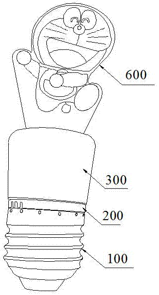
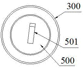
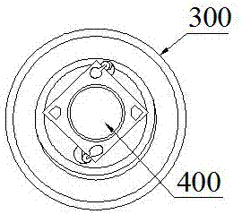
[0016] refer to Figure 1 to Figure 4 , an embodiment of a new type of personalized light bulb of the present invention is proposed, including a lamp cap nut 100, an insulating seat 200 located at the upper end of the lamp cap nut 100, and a lamp body 300 with a variety of designs located at the upper end of the insulating seat 200 , the COB light source 400 arranged inside the lamp body 300 and illuminating upwards, the driving device arranged in the lamp cap nut 100 and electrically connected between the COB light source 400 and the lamp cap nut 100, embedded in the lamp body 300 and located The mounting base 500 above the COB light source 400 is snapped and fixed on the upper end of the mounting base 500 and can be replaced with a light guide plate 600 with various designs.

[0017] The mounting base 500 is provid...


PUM


Abstract

The invention discloses a novel personalized bulb. The novel personalized bulb comprises a bulb holder nut, an insulation seat, a bulb body, a COB light source, a driving device, a mounting seat and alight guide plate, wherein the insulation seat is arranged at the upper end of the bulb holder nut; the bulb body is arranged at the upper end of the insulation seat and is capable of being designedin a diversified mode; the COB light source is arranged inside the bulb body and irradiates upwards; the driving device is arranged in the bulb holder nut; the mounting seat is embedded in the bulb body and located on the upper portion of the COB light source; and the light guide plate is clamped at the upper end of the mounting seat and is capable of being replaced and designed in a diversified mode. A clamping groove which can be used for light emitting and fixed to the light guide plate in a clamped mode is formed in the position, corresponding to the COB light source, of the mounting seat.A fixed block capable of being inserted into the clamping groove in a clamped mode is arranged at the lower end of the light guide plate in an extending mode. A stereo or plane pattern capable of being customized in a personalized mode is arranged on the light guide plate, and drawing and writing can be conducted on the light guide plate through a highlighter. Light emitted by the COB light source irradiates onto the light guide plate through the clamping groove to enable the light guide plate to overall emit the light outwards and take the illuminating effect, meanwhile the pattern on the light guide plate emits the light, and thus the light-emitting pattern with the illuminating and ornamental effects is formed.

Description

technical field [0001] The invention relates to the technical field of lamps, in particular to a novel personalized light bulb. Background technique [0002] Bulbs are widely used in various places. The structure of the existing light bulbs generally includes a lamp cap nut, an insulating seat on the lamp cap nut, a lamp body on the upper end of the insulating seat, and an LED light source on the upper end of the lamp body. structure of the light source column, the driving device located in the lamp holder, and the light transmission cover that is connected and fixed on the lamp body and covers the light source column. It can be seen that the existing light bulbs are generally directed to the LED light source structure. The way is easy to dazzle and glare, and the light output effect is not ideal; in addition, the existing light bulbs generally only have lighting function, the structure is traditional and old, the function is single, the style is dull, and the lack of apprec...

Claims


Application Information

Patent Timeline
Patent Type & Authority Applications(China)
IPC IPC(8): F21K9/232F21V8/00F21K9/61F21V17/16F21Y115/10
Inventor 李耿聪
Owner 李耿聪
Why Eureka
Try Eureka