System and method for pulsed based receiver photo sensor

A photoelectric sensor and pulse technology, applied in the field of photoelectric sensors, can solve the problems of difficult synchronization between the receiver and the transmitter, the inability to easily exchange synchronous data, sensitivity to repetitive noise, etc.

Active Publication Date: 2018-01-12
ROCKWELL AUTOMATION TECH
View PDF4 Cites 5 Cited by
  • Summary
  • Abstract
  • Description
  • Claims
  • Application Information

AI Technical Summary

Problems solved by technology

However, in the absence of proper synchronization, this technique makes the sensor's receiver sensitive to any repetitive noise with an energy level similar to that of the modulated pulse
[0004] Furthermore, in the case of through-beam sensors, synchronization between the receiver and transmitter is difficult because the receiver and transmitter of such through-beam sensors reside in physically separate housings. body, and therefore cannot easily exchange synchronized data
[0005] The above-mentioned deficiencies of current photosensors are only intended to provide an overview of some of the problems of conventional systems, and are not intended to be exhaustive

Method used


Image

  • System and method for pulsed based receiver photo sensor
  • System and method for pulsed based receiver photo sensor
  • System and method for pulsed based receiver photo sensor

Examples


Embodiment Construction

[0028] The present disclosure is now described with reference to the drawings, wherein like reference numerals are used to refer to like elements throughout. In the following description, for purposes of explanation, numerous specific details are set forth in order to provide a thorough understanding of the present disclosure. It is, however, evident that the present disclosure may be practiced without these specific details. In other instances, well-known structures and devices are shown in block diagram form in order to facilitate describing the present disclosure.

[0029] As used in this application, the terms "component", "system", "platform", "layer", "controller", "terminal", "station", "node", "interface" are intended to refer to A computer-related entity, or an entity relating to or being part of an operating device having one or more specific functions, where such an entity may be hardware, a combination of hardware and software, software, or an operating software....


PUM


Abstract

A photo sensor, a method of operating the photo sensor, and a non-transitory computer readable medium are disclosed. A photoelectric sensor uses a selective pulse detection technique and associated synchronization techniques to improve the quality of pulse detection, the operating range of the sensor, and the sensor's immunity to noise. These improvements also yield faster sensor response times and reduce the design cycle time. A modulated light beam emitted by the sensor's emitter comprises multiple pulse periods, with a pulse being transmitted within each period. The pulses are positioned within their respective periods at a defined offset time relative to the start of the periods, where the offset time can vary between periods according to a defined pattern. The receiver can selectivelysample the signal based on synchronization information to determine whether the received signal contains the emitted pulse pattern. Through-beam sensor embodiments can generate the synchronization information internally based on an analysis of the analog signal corresponding to the modulated signal.

Description

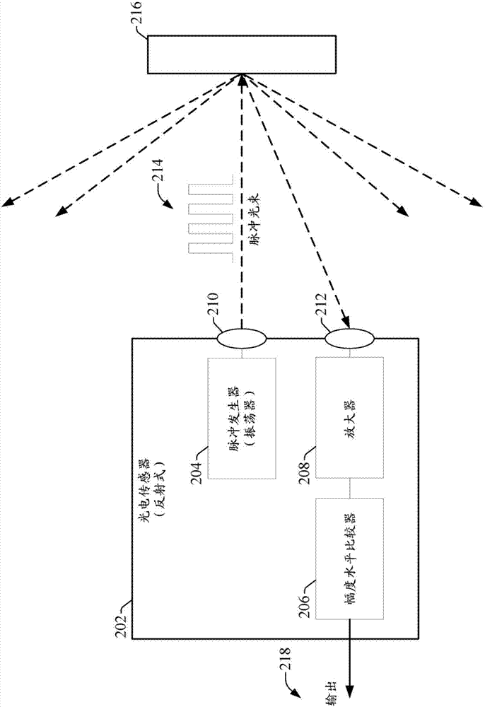
technical field [0001] The subject matter disclosed herein relates generally to photoelectric sensors, and more specifically to the detection of modulated pulse signals at the sensor's receiver. Background technique [0002] Many industrial applications utilize photoelectric sensors to detect the presence of objects or people at certain locations around a controlled process or machine. For example, such sensors may be installed at selected conveyor locations to detect the presence of components at those locations. Such photoelectric sensors can also be installed near potentially hazardous moving parts of industrial systems to detect the presence of people at these locations. These sensors typically control discrete outputs to a control system (eg, industrial controllers, safety relays, etc.) based on the detection of the transmitted light beam at the receiver. [0003] For photosensors that use light pulse modulation, the receiver typically detects the modulated pulses car...

Claims


Application Information

Patent Timeline
Patent Type & Authority Applications(China)
IPC IPC(8): G01V8/12
CPCG01V8/12H04B10/40H04B10/50H04B10/60G02B6/3598H01S3/00H04B1/7174H04B7/17H04B10/691
Inventor 唐纳德·L·查兰蒂尼格雷戈里·J·赖曼德里克·W·加伦弗雷德里克·鲍陶德
Owner ROCKWELL AUTOMATION TECH
Why Eureka
Try Eureka