an antenna

An antenna and antenna support technology, applied in the field of electronics, can solve problems such as narrow bandwidth, and achieve the effects of reducing inductance, reducing radiation impedance, and improving radiation efficiency

Active Publication Date: 2022-01-25
GUANGDONG OPPO MOBILE TELECOMM CORP LTD
View PDF11 Cites 0 Cited by
  • Summary
  • Abstract
  • Description
  • Claims
  • Application Information

AI Technical Summary

Problems solved by technology

But IFA has the same disadvantage as the microstrip antenna, which is narrow bandwidth.

Method used


Image

  • an antenna
  • an antenna
  • an antenna

Examples


Embodiment Construction

[0018] The following will clearly and completely describe the technical solutions in the embodiments of the present invention with reference to the accompanying drawings in the embodiments of the present invention. Obviously, the described embodiments are some of the embodiments of the present invention, but not all of them. Based on the embodiments of the present invention, all other embodiments obtained by persons of ordinary skill in the art without creative efforts fall within the protection scope of the present invention.

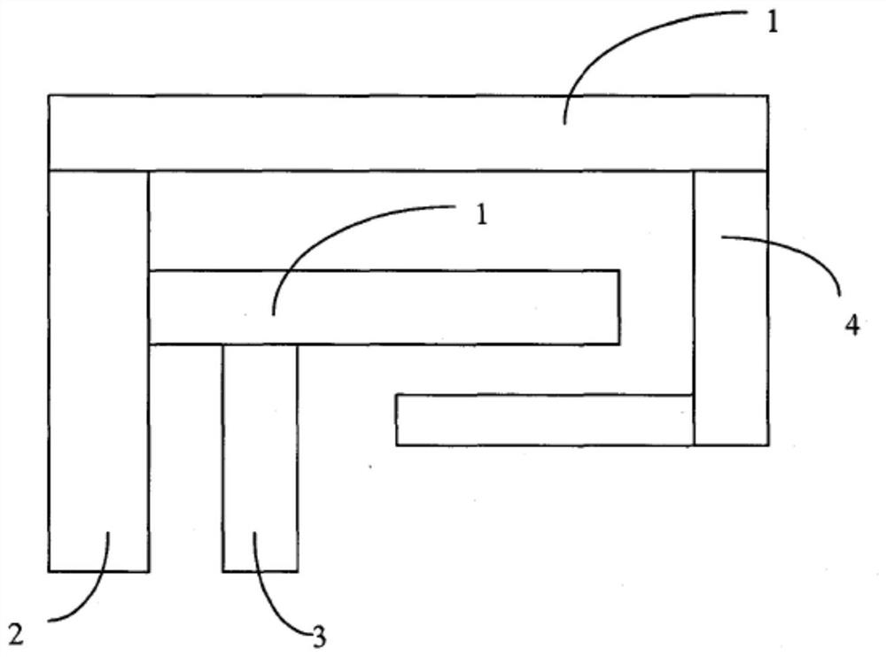
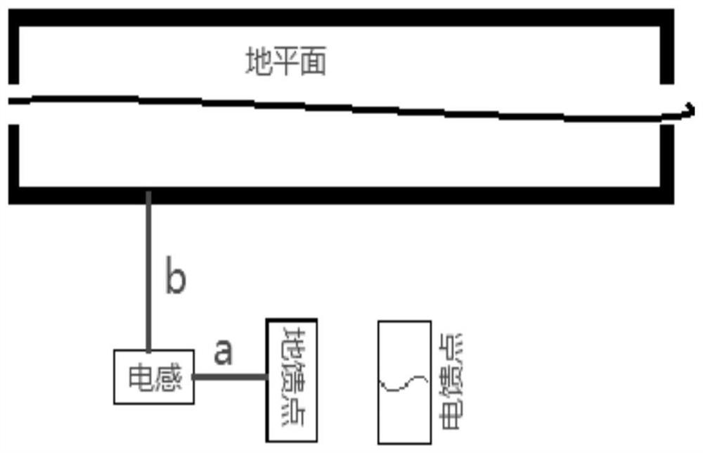
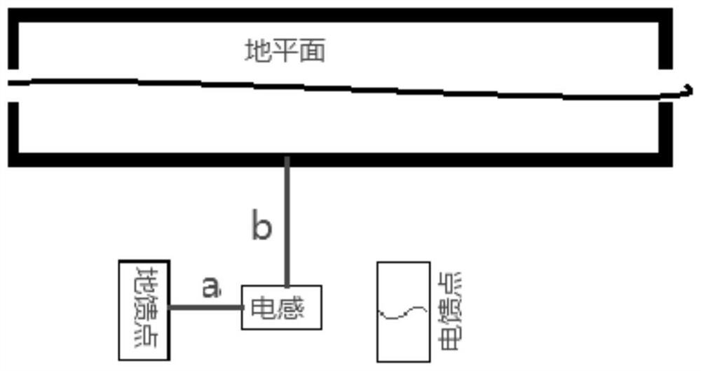
[0019] Please refer to figure 2 , figure 2 It is a schematic structural diagram of the first embodiment of an antenna proposed by the embodiment of the present invention. As shown in the figure, the antenna radiator includes an inductor, an electric feed point, and a ground feed point, the inductor, the electric feed point, and the ground feed point are arranged side by side, and the connection between the inductor and the ground feed point The lin...


PUM


Abstract

The invention discloses an antenna, comprising: an antenna bracket and an antenna radiator, the antenna radiator includes an inductor, an electric feed point, and a ground feed point, and the inductor, the electric feed point, and the ground feed point are arranged side by side The connection line between the inductance and the ground feed point is arranged parallel to the trace on the antenna support, and the distance between the inductance and the ground feed point connection line is adjustable. By adopting the embodiment of the present invention, not only the radiation efficiency of the antenna can be guaranteed, but also the low-frequency bandwidth can be widened.

Description

technical field [0001] The invention relates to the field of electronic technology, in particular to an antenna. Background technique [0002] With the popularization of LTE (Long Term Evolution, Long Term Evolution) technology, the bandwidth required to be supported by the antenna is getting wider and wider. But at the same time, users have higher requirements on the appearance of electronic equipment, which makes electronic equipment more and more miniaturized and thinner. In this case, the antenna space of the electronic equipment is also being gradually compressed, and the antenna space is basically proportional to the bandwidth. Therefore, it becomes a difficult problem to achieve a wider bandwidth in a smaller antenna space. [0003] The current mobile phone antenna is divided into two types: external and built-in. The built-in mobile phone antenna is placed inside the mobile phone, such as IFA (Inverted-F Antenna, inverted F antenna) type antenna, of which PIFA (Plan...

Claims


Application Information

Patent Timeline
Patent Type & Authority Patents(China)
IPC IPC(8): H01Q1/36H01Q1/50H01Q1/12
Inventor 向元彬
Owner GUANGDONG OPPO MOBILE TELECOMM CORP LTD
Why Eureka
Try Eureka