Flexible Printed Antenna

a flexible, printed technology, applied in the direction of antennas, antenna details, basic electric elements, etc., can solve the problems of increasing the difficulty of embedding and wiring feeder cables, affecting the fabrication efficiency of antennas, and affecting the reliability of antennas, so as to achieve the effect of better flexibility

Inactive Publication Date: 2011-06-30
ADVANCED CONNECTEK INC
View PDF3 Cites 7 Cited by
  • Summary
  • Abstract
  • Description
  • Claims
  • Application Information

AI Technical Summary

Benefits of technology

[0007]One objective of the present invention is to provide a flexible printed antenna, wherein a flexible substrate of the antenna adopts a FPCB (Flexible Printed Circuit Board) material, and wherein a radiation conductor and a feeder cable are directly formed on the surface of the flexible substrate, whereby the antenna module has a better flexibility and applies to the curved structures of various communication products.
[0008]Another objective of the present invention is to provide a flexible printed antenna, wherein a flexible printed circuit board, a printed radiation conductor and a printed flexible feeder cable are integrated into a thin antenna module, whereby is formed a multi-layer antenna structure, greatly reduced the thickness of the antenna, and increased the convenience of assembling the antenna module.
[0009]A further objective of the present invention is to provide a flexible printed antenna, wherein the feeder cable is integrated with the antenna, whereby the feeder cable does not occupy additional space, and whereby the radiation area of the antenna is greatly increased, and whereby the performance and radiation efficiency of the antenna is greatly promoted.
[0010]A further another objective of the present invention is to provide a flexible printed antenna, wherein the flexible feeder cable is directly printed on a flexible substrate without soldering and wiring, whereby the antenna module is easy to bend, and whereby the fabrication time and cost is effectively reduced.
[0012]In a first embodiment of the present invention, the flexible substrate adopts a FPCB material and cooperates with the primary conductor, secondary conductor and flexible feeder cable to form a super-thin antenna module, wherein the flexible feeder cable is integrated with the antenna structure, whereby is greatly reduced the whole thickness of the antenna, and whereby are increased the radiation area, performance and radiation efficiency of the antenna, wherefore is expanded the application field of the antenna. As the elements of the antenna module are all made of flexible materials, the entire antenna module has superior flexibility. Thus, the present invention applies to the non-planar structures of various communication products. Besides, the flexible feeder cable is directly printed on the surface of the flexible substrate without the wiring and soldering processes that are required in the conventional technology. Therefore, the present invention can effectively reduce the time and cost of fabrication.

Problems solved by technology

When signals are simultaneously transmitted in the feeder cables, they are likely to interfere with each other.
Further, the feeder cables are very long, which increases the difficulties in embedding and wiring the feeder cables and prolongs the fabrication time of the antenna.

Method used


Image

  • Flexible Printed Antenna
  • Flexible Printed Antenna
  • Flexible Printed Antenna

Examples


Embodiment Construction

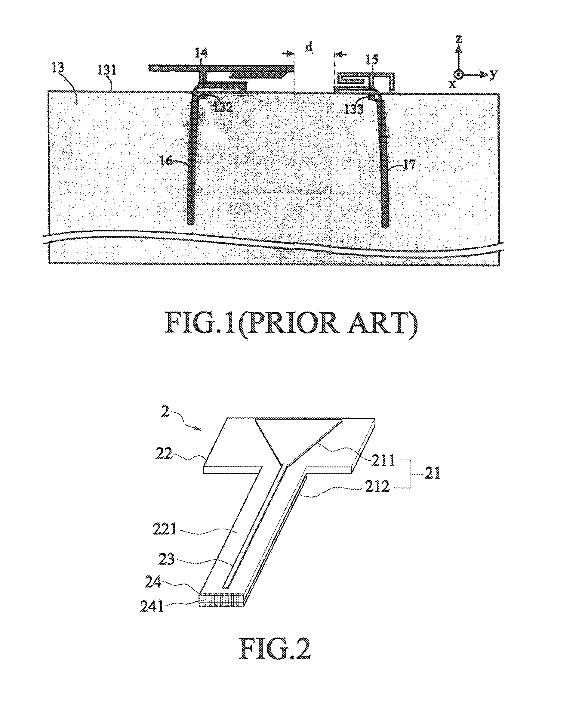
[0022]Refer to FIG. 2 a perspective assembly drawing of a flexible printed antenna according to a first embodiment of the present invention. The antenna module 2 of the present invention comprises a radiation conductor 21, a flexible substrate 22, a flexible feeder cable 23 and a grounding member 24. The radiation conductor 21 includes a primary conductor 211 and a secondary conductor 212. The grounding member 24 has a plurality of through-holes 241 reaching the secondary conductor 212 and used to conduct the electrical signals between the secondary conductor 212 and the grounding member 24.

[0023]The flexible substrate 22 adopts a FPCB material. The primary conductor 211 and the secondary conductor 212 are respectively printed on the upper surface 221 and the lower surface 222 (not shown in the drawing) with the flexible substrate 33 interposed between the primary conductor 211 and the secondary conductor 212 to form the main structure of the radiation conductor of the antenna. The ...


PUM


Abstract

A flexible printed antenna comprises a flexible substrate, a radiation conductor, a flexible feeder cable and a grounding member. The radiation conductor includes a primary conductor and at least one secondary conductor. The flexible substrate is interposed between the primary conductor and the secondary conductor. One end of the feeder cable connects with the primary conductor, and another end extends far away from the primary conductor and connects with the signal source. The present invention is characterized in adopting a flexible substrate made of a FPCB material and forming a radiation conductor and a flexible feeder cable on different surface of the flexible substrate. Thereby, the antenna module of the present invention has better flexibility and applies to various non-planar structures of various communication products. Further, the present invention can be fabricated into a multi-layer antenna structure to greatly reduce the thickness of the antenna.

Description

BACKGROUND OF THE INVENTION[0001]1. Field of the Invention[0002]The present invention relates to a flexible printed antenna, particularly to a flexible multi-layer antenna structure.[0003]2. Description of the Related Art[0004]The wireless communication technology is developing rapidly, and the tendency of antenna design is to meet the miniaturization and multiband requirements of the communication devices. Thus, different types of antennae are integrated into a single antenna module to satisfy the strict design standard of antennae.[0005]Refer to FIG. 1 a diagram schematically a conventional integrated antenna for a dual-network communication device. The integrated antenna comprises a grounding plane 13, a first antenna 14, a second antenna 15, a first coaxial feeder cable 16 and a second coaxial feeder cable 17. The rectangular grounding plane 13 has a first grounding point 132 and a second grounding point 133. The first antenna 14 is arranged near the top edge 131 of the groundin...

Claims


Application Information

Patent Timeline
Patent Type & Authority Applications(United States)
IPC IPC(8): H01Q9/04
CPCH01Q1/38H01Q9/40
Inventor CHIU, TSUNG-WENHSIAO, FU REN
Owner ADVANCED CONNECTEK INC
Why Eureka
Try Eureka