T-type superpower ultrasonic transducer

An ultrasonic and transducer technology, which is applied in the field of T-type high-power ultrasonic transducers, can solve the problem of large vibration speed, vibration displacement and longitudinal stress of the transducer, limiting the acoustic wave radiation area of ​​the transducer, and radiated power and radiated power. and sound wave radiation area limitation, to achieve the effect of large diameter, high power operation, and improved radiation efficiency

Inactive Publication Date: 2013-07-24
SHAANXI NORMAL UNIV
View PDF2 Cites 7 Cited by
  • Summary
  • Abstract
  • Description
  • Claims
  • Application Information

AI Technical Summary

Problems solved by technology

[0003] 1. The design theory of the longitudinal sandwich ultrasonic transducer requires that the transverse dimension of the transducer, that is, the diameter, cannot exceed a quarter of the wavelength of the sound wave radiated by the transducer, so the sound wave radiation area of ​​this type of transducer is limited The limitation of its own theory cannot exceed a certain limit, which greatly limits the acoustic radiation area and radiation power of this type of transducer
[0004] 2. For the sandwich-type longitudinal vibration piezoelectric ceramic ultrasonic transducer, due to the limitation of the radiation area, the sound intensity of the transducer is also very large under the condition of large radiation power, which leads to the vibration speed inside the transducer, The vibration displacement and longitudinal stress are also very large, sometimes exceeding the mechanical strength limit of the material, resulting in the fracture or damage of the transducer
[0005] In view of the above problems, in order to adapt to the rapid development of ultrasonic technology, it is necessary to develop a new type of power ultrasonic transducer to overcome some outstanding problems of the current sandwich-type longitudinal vibration ultrasonic transducer, that is, the limitation of radiation power and acoustic radiation area question

Method used


Image

  • T-type superpower ultrasonic transducer

Examples


Embodiment 1

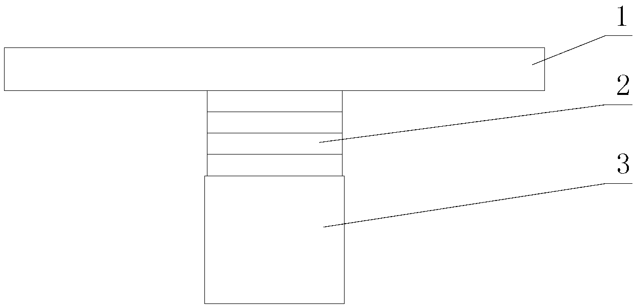
[0017] This embodiment takes the T-type high-power ultrasonic transducer of 20 kilohertz as an example, by figure 1 It can be seen that the ultrasonic transducer in this embodiment is composed of a vibration plate 1 , a piezoelectric ceramic stack 2 and a rear cover 3 .

[0018] The vibrating plate 1 of this embodiment is made of high-strength, low-loss light metal material. This implementation is made of aluminum alloy material. Its geometric shape is a disc shape, its diameter is 180 mm, and its thickness is 18 mm. The central position of the piezoelectric ceramic stack 2 is connected by high-strength metal bolts. The piezoelectric ceramic stack 2 is composed of 4 piezoelectric ceramic sheets coaxially stacked into a cylinder with a thickness of 24mm. The thickness of each piezoelectric ceramic sheet is The diameter is 6mm, and the diameter is 60mm, that is, the diameter of the vibrating plate 1 is three times the diameter of the piezoelectric ceramic sheet, and the piezoele...

Embodiment 2

[0020] This embodiment takes the T-shaped high-power ultrasonic transducer of 25 kHz as an example. The geometric shape of the vibration plate 1 is a disc shape, its diameter is 260 mm, and its thickness is 21 mm. The metal bolts are connected with a piezoelectric ceramic stack 2. The piezoelectric ceramic stack 2 is coaxially stacked with 4 piezoelectric ceramic sheets to form a cylinder with a thickness of 24mm. Each piezoelectric ceramic sheet has a thickness of 6mm and a diameter of 50mm. That is, the diameter of the vibrating plate 1 is 5.2 times the diameter of the piezoelectric ceramic sheet, and the piezoelectric ceramic sheets are bonded and fixed by superglue, and a rear cover 3 is fixed on the other end of the piezoelectric ceramic stack 2, and the rear cover 3 adopts Made of high-strength, low-loss steel material, its geometric shape is disc-shaped, with a diameter of 52mm, which is 1.04 times the diameter of the piezoelectric ceramic sheet, and the height of the re...

Embodiment 3

[0022] This embodiment takes the T-shaped high-power ultrasonic transducer of 30 kHz as an example. The geometric shape of the vibrating plate 1 is a disc shape, its diameter is 206 mm, and its thickness is 15 mm. The metal bolts are connected with a piezoelectric ceramic stack 2. The piezoelectric ceramic stack 2 is coaxially stacked with 4 piezoelectric ceramic sheets to form a cylinder with a thickness of 24mm. Each piezoelectric ceramic sheet has a thickness of 6mm and a diameter of 50mm. That is, the diameter of the vibrating plate 1 is 4.12 times the diameter of the piezoelectric ceramic sheet, and the piezoelectric ceramic sheets are bonded and fixed by superglue, and a rear cover 3 is fixed on the other end of the piezoelectric ceramic stack 2, and the rear cover 3 adopts Made of high-strength, low-loss steel material, its geometric shape is disc-shaped, with a diameter of 52mm, which is 1.04 times the diameter of the piezoelectric ceramic sheet, and the height of the r...


PUM


Abstract

The invention relates to a T-type superpower ultrasonic transducer. The T-type superpower ultrasonic transducer utilizes a longitudinal vibration piezoelectric ceramic vibrator to generate longitudinal vibration, stimulates a metal round vibration disc directly connected with the longitudinal vibration piezoelectric ceramic vibrator to generate the vibration of the same frequency, and radiates sound waves to media. With the help of the conversion of the vibration mode, flexural vibration is generated in the metal round vibration disc, effective conversion of the longitudinal vibration mode and the flexural vibration mode is achieved, uniformity of the radiation sound field of the transducer is greatly improved, radiation area of the transducer can be effectively increased, high-power working is realized, at the same time, radiation impedance of the transducer is improved, acoustic matching of the transducer is improved, and radiation efficiency of the transducer is improved. In addition, due to the fact that the flexural vibration disc has multiple vibration modes, the transducer can work in different vibration modes and radiate ultrasonic waves of different frequencies, and therefore an ultrasonic wave source working in multiple frequencies is formed.

Description

technical field [0001] The invention belongs to the technical field of research on generation or transmission equipment of ultrasonic frequency mechanical vibrations, and in particular relates to a T-shaped high-power ultrasonic transducer. Background technique [0002] In the field of power ultrasound and underwater acoustics, longitudinal vibration sandwich piezoelectric ceramic ultrasonic transducers, also known as Langevin transducers, are widely used, such as ultrasonic cleaning, ultrasonic metal and plastic welding, ultrasonic processing, etc. . Its structure is mainly to install a piezoelectric ceramic sheet in the middle of the prestressed bolt. One end of the prestressed bolt is provided with a metal front cover, and the other end is provided with a metal back cover. The structure of the front cover is a conical platform structure. This type of transducer has high electromechanical conversion efficiency and large power capacity. However, due to the theoretical and...

Claims


Application Information

Patent Timeline
Patent Type & Authority Applications(China)
IPC IPC(8): B06B1/06
Inventor 林书玉
Owner SHAANXI NORMAL UNIV
Why Eureka
Try Eureka