Automatic bothway sand-blasting machine

A sandblasting machine and automatic technology, applied in the field of sandblasting machines, can solve the problems of quartz sand waste, difficulty in collection, dust explosion, etc., achieve the effect of large sandblasting radiation area, improve processing efficiency, and reduce processing costs

Active Publication Date: 2017-05-24
ZHEJIANG IND & TRADE VACATIONAL COLLEGE
View PDF5 Cites 7 Cited by
  • Summary
  • Abstract
  • Description
  • Claims
  • Application Information

AI Technical Summary

Problems solved by technology

[0003] The traditional sandblasting machine includes a shell, in which there is a sandblasting chamber, and a sandblasting head is arranged in the sandblasting chamber. When the pipe is pushed in from one side of the sandblasting chamber, the sandblasting head sprays quartz sand on the pipe, and the quartz The sand collides with the outer periphery of the pipe fittings to remove the dirt and rust stains on the outer periphery of the pipe fittings. The above-mentioned sandblasting machine has the following problems: ①After the quartz sand hits the pipe fittings, it will generate dust, which will pollute the working environment around the sandblasting machine. On the one hand, the dust It is easy to cause explosion, and on the other hand, it affects the health of the staff; ②The quartz sand is vertically impacted on the outer circumference of the pipe fittings, and most of the quartz sand is rebounded by the pipe fittings after the impact, resulting in low processing efficiency of the quartz sand and serious waste of quartz sand; ③It is difficult to collect quartz sand after use, and it is often discarded after sorting out, which increases the production cost; ④After the pipe fitting enters the sandblasting room, it will not rotate automatically, and it can only be blasted at the same time by setting the sandblasting head in multiple directions, resulting in the same mechanism duplication and complexity of the internal structure

Method used


Image

  • Automatic bothway sand-blasting machine
  • Automatic bothway sand-blasting machine
  • Automatic bothway sand-blasting machine

Examples


Embodiment Construction

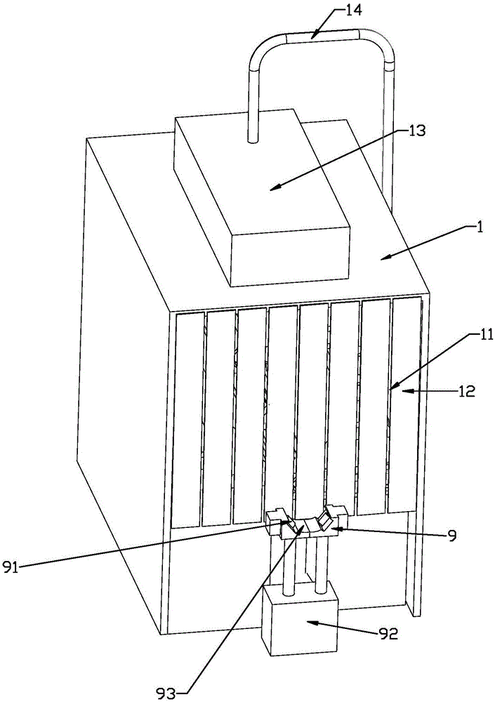
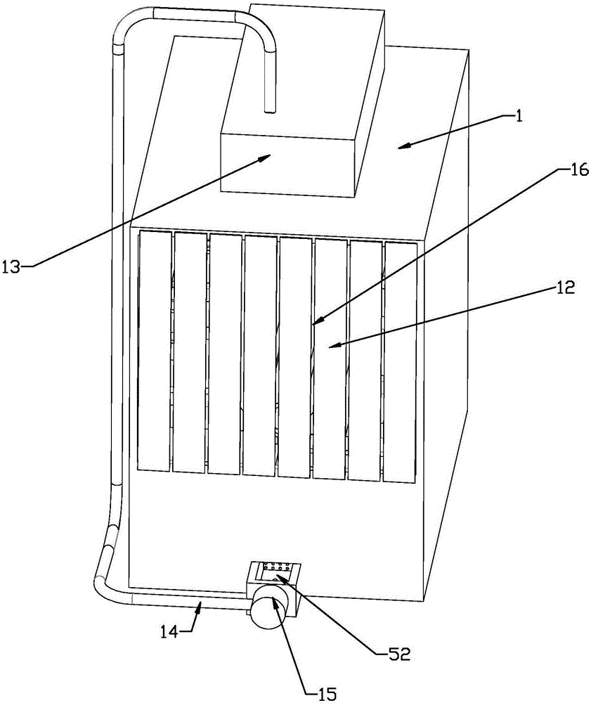
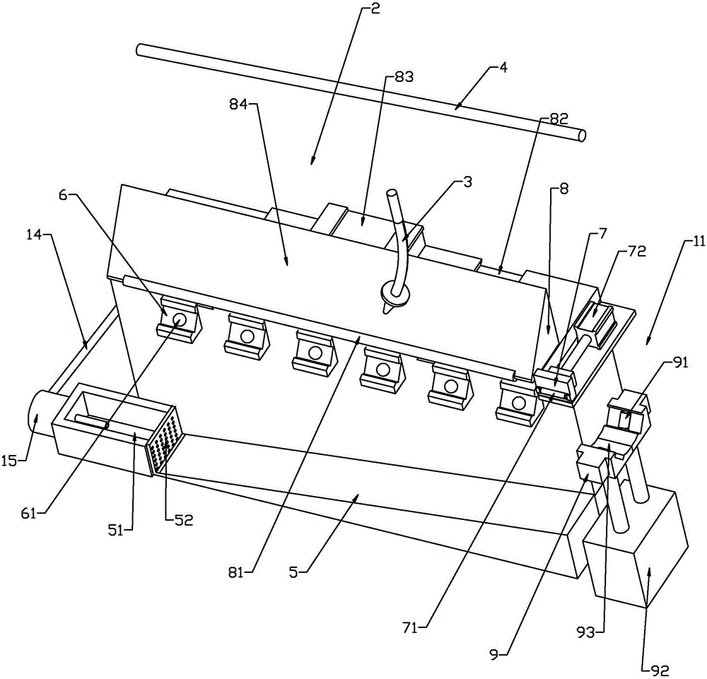
[0018] Such as figure 1 — Figure 4 As shown, the present invention discloses a two-way automatic sandblasting machine, comprising a housing 1, figure 2 The sandblasting chamber 2 is only located on one side of the pipeline, and the other side is symmetrically arranged with respect to the pipe body. The shell 1 is provided with a sandblasting chamber 2, and sandblasting heads 3 are arranged in the sandblasting chamber 2. The casing 1 is provided with a push port 11 for pushing pipe fittings into the sandblasting chamber 2 and a delivery port 16 for sending out of the sandblasting chamber. The casing 1 is located at the push port 11 and the delivery port 16 and is respectively provided with a dust-proof part covering the push port 11. , the dust-proof part is composed of several dust-proof units 12 arranged in sequence along the transverse direction of the push-in port 11. The dust-proof units 12 are made of soft materials and hang down naturally. The circulation device incl...


PUM


Abstract

The invention relates to an automatic bothway sand-blasting machine. The automatic bothway sand-blasting machine comprises a shell internally provided with a sand-blasting chamber. Sand-blasting heads are arranged in the sand-blasting chamber. The shell is provided with a push inlet through which a pipe is pushed into the sand-blasting chamber, and a conveying outlet through which the pipe is conveyed out of the sand-blasting chamber. Dustproof parts covering the push inlet are arranged on the parts, located at the push inlet and the conveying outlet, of the shell correspondingly. A water curtain circulating device is arranged in the shell and comprises a water spraying pipeline and a circulating water tank. The sand-blasting chamber is provided with a secondary grinding device for grinding through secondary use of blasting sand. The shell is provided with an adjusting mechanism used for adjusting the orientation of the sand-blasting heads. Through the scheme, the automatic bothway sand-blasting machine provided by the invention is high in quartz sand processing efficiency and capable of preventing flying dust from polluting the working environment.

Description

technical field [0001] The invention relates to a sandblasting machine, in particular to a two-way automatic sandblasting machine. Background technique [0002] Due to the impact and cutting effect of abrasives on the surface of the workpiece, the surface of the workpiece can be obtained with a certain degree of cleanliness and different roughness, so that the mechanical properties of the surface of the workpiece are improved, thus improving the fatigue resistance of the workpiece and increasing its The adhesion between the coating and the coating prolongs the durability of the coating film, and is also conducive to the leveling and decoration of the coating. It removes impurities, variegated colors and oxide layers on the surface, and at the same time roughens the surface of the medium to eliminate the residual stress of the workpiece. and improve the surface hardness of the substrate. [0003] The traditional sandblasting machine includes a shell, in which there is a sand...

Claims


Application Information

Patent Timeline
Patent Type & Authority Applications(China)
IPC IPC(8): B24B5/36B24C3/02B24C9/00
CPCB24B5/36B24C3/02B24C9/00B24C9/003B24C9/006
Inventor 徐临超林继兴吴金蔚梅潇伟
Owner ZHEJIANG IND & TRADE VACATIONAL COLLEGE
Why Eureka
Try Eureka